The need to study the coupled behavior between fluids and structures in the presence of heat effects arises in many applications, including heat exchangers, disc brake cooling, components mounted on printed circuit boards, and coolant pipes in power plants, among others.
ADINA offers both one-way and two-way thermal coupling in fluid-structure interaction (FSI) analysis. In one-way thermal coupling (or conjugate heat transfer) FSI analysis, the energy equation is solved entirely by the fluid solver, without accounting for the heat generation in the solid. In this method, heat flows from the fluid to the solid domain. In two-way thermal couping FSI analysis, referred to simply as thermal FSI (or TFSI) analysis, the energy equation is solved separately in the fluid and solid domains, and the domains are coupled together by enforcing the same temperature and heat flux at the fluid-structure interface. In TFSI analysis, the fluid and solid domains are fully coupled.
One major advantage of TFSI analysis is that heat generation in the solid model (i.e., due to frictional heating, plastic deformation, or viscous effects) affects the temperature field of the fluid model. In many applications, this yields results that reflect more closely the multiphysics aspects of the problem.
Figure 1 below represents a plate-frame heat exchanger modeled using the TFSI feature in ADINA. The structural domain comprises the corrugated steel plates, while the fluid domain comprises the hot and cold sides of the exchanger.
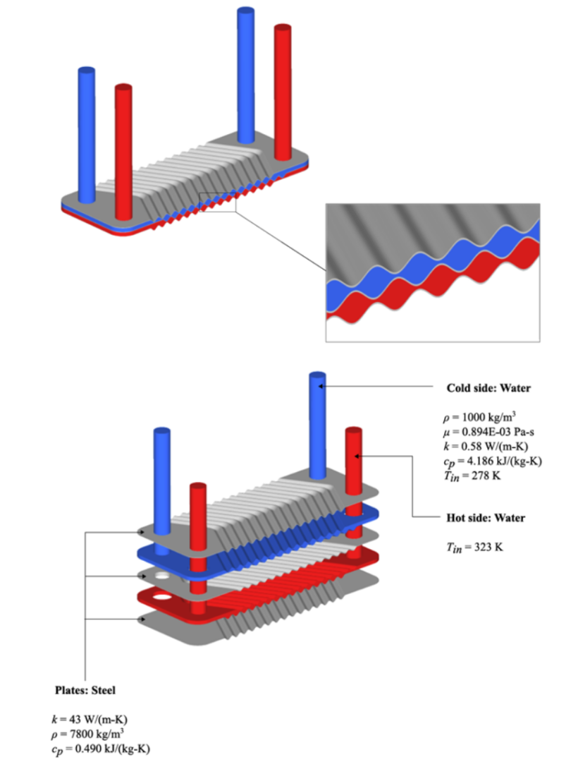 Figure 1 Schematic diagram of the three-plate plate-frame heat exchanger considered
The temperatures along the FSI boundaries, where the plates contact the fluids is displayed in Figure 3:
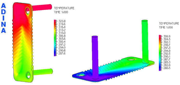
Figure 3 Band plot highlighting temperatures along the FSI boundaries
The heat transfer coefficient of the exchanger can be calculated from the ADINA results using the following formula:
![]()
where Q is the heat transferred, A is the surface area available for heat transfer, U is the overall heat transfer coefficient, and ΔTLM is the logarithmic mean temperature difference.
The logarithmic mean temperature difference is given by the following formula:
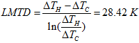
and hence the heat transfer coefficient is calculated by the following:
![]()
The heat transfer coefficient for this three plate exchanger is in the typical range (1000 – 4000 W/(m2 K)) for a liquid-liquid plate-frame heat exchanger.
The TFSI feature in ADINA offers fully coupled fluid-structure interaction capabilities in which heat effects are accounted for both in the fluid and the solid models. Such cases are common in industry, making ADINA the preferred multiphysics solution to modeling a wide-reaching class of problems.
Keywords:
Fluid-structure interaction, FSI, thermal fluid-structure interaction, TFSI, plate-frame heat exchanger