It is often desirable to replace complex or expensive solid element models with structural elements possessing equivalent mechanical responses. Beam, truss, and spring elements are a few familiar examples, and they can be used in many circumstances. However, the response of bushings, bearings, ball joints, or structural components with general geometries, etc. can be more complex, with different and potentially nonlinear stiffness and/or damping responses in different degrees of freedom. Such cases cannot be modeled accurately with traditional structural elements. ADINA’s new connector element was developed to provide users with a convenient tool for these cases, and many others.
The connector element is a 2-node large displacement generalized spring/damper element with linear or nonlinear material properties. Furthermore, the connector element possesses a user-defined convecting local coordinate system such that for rigid body motions, the relative nodal positions and orientations (local displacements and rotations) remain unchanged, and the element’s internal forces transform with the rigid body motions. In other words, the response of the structure being modeled will be preserved under rigid body motions. For example, a connector element modeling a shock absorber will predict the same response (relative to its attached local coordinate system) regardless of its orientation.
Modeling Case
The following example demonstrates how a 3D solid finite element model of a light truck suspension component, complete with connecting bushings, can be replaced using 3 connector elements which provide the equivalent structural response at a small fraction of the computational cost.
Figure 1 illustrates the components under consideration in relation to the vehicle’s front axle. The inset in Figure 1 details these components.
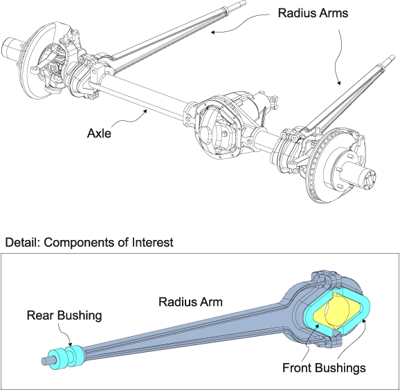
Figure 1 Suspension components under consideration, with detailed inset. The inset shows the 3D solid model of the radius arm (grey) and its attached bushings (blue). The radius arm is steel and linearly elastic. The bushings are rubber (large strain hyperelasticity, incompressible).
Joint Connector Elements
A connector element may be used to model linear or nonlinear joint behavior, with separate, arbitrary responses for each of its six local degrees of freedom. The element’s nodes may be initially separated or coincident, and the user may arbitrarily define the element’s local coordinate system and undeformed state.
Figure 2 shows a cutaway view of the rear rubber bushing and steel shaft connection. As the connection undergoes large relative translations and rotations, the rubber bushing experiences large strains. Also, because the steel and the rubber materials both possess high bulk moduli, the steel shaft undergoes moderate bending. By modeling this interaction, it is possible to obtain an accurate response of the joint.
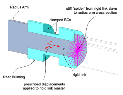
Given a set of prescribed displacements and rotations, a corresponding set of reaction forces and moments can be obtained from the 3D solid finite element model. These displacements and reactions can then be used to define the equivalent connector element’s nonlinear force-displacement responses in each of its six local degrees of freedom. Figure 3 (top) shows the rear bushing/radius arm connection as it articulates under prescribed translations and rotations. The equivalent connector element is shown (Figure 3, bottom) undergoing the same prescribed translations and rotations.
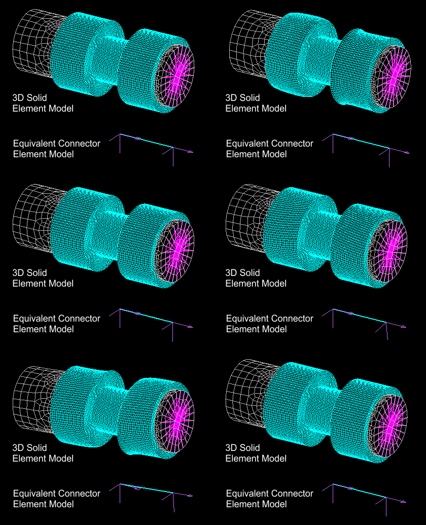
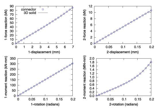
Figure 4 shows the comparison of the responses predicted by the 3D solid model and the connector element model. As can be seen, the responses of the 3D-solid model and the equivalent connector element are identical. The response for the front bushing is obtained in a similar manner.
Matrix Connector Element
The connector element also allows for the user to directly specify the structure’s stiffness matrix relative to the structure’s local coordinate system (which the user can specify in several ways). The connector element will provide the same response (with respect to its attached coordinate system) for any orientation or position as it moves in space (the connector element is always a large displacement/rotation element).
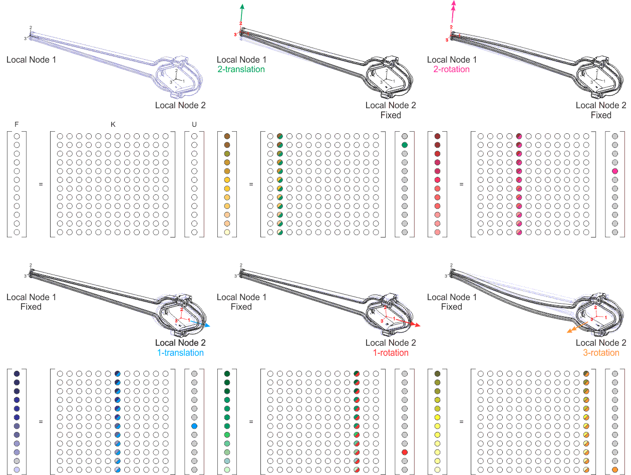
It is easy to extract the stiffness matrix from an arbitrary structure by subjecting it to a series of small prescribed displacements at its 2 points of attachment (these points of attachment correspond to the connector element’s nodes). Each prescribed displacement in the local degree of freedom provides 12 reaction forces and moments, which gives a column in the 12×12 stiffness matrix. Figure 5 illustrates the process of interrogating the structure and populating the stiffness matrix.
Figure 5 Illustration of the process used for obtaining the 12×12 stiffness matrix [K] corresponding to a connecting structure. The connecting structure (in this case, the radius arm) is assumed to possess a linear response. It is attached at two locations (in this case, surfaces), which will correspond to local nodes 1 and 2 of the connector element. Each node is connected to the proximate connecting surfaces of the structure via a rigid link spider (not shown here, for clarity). Each node is then subjected to a series of small displacements and rotations while the other node is held fixed. During loading, the force and moment reactions at local nodes 1 and 2 are obtained. By dividing each of the 12 reactions by the prescribed displacement, a column of the stiffness matrix is obtained. The motions have been greatly exaggerated for clarity.
Complete Connector Element Model
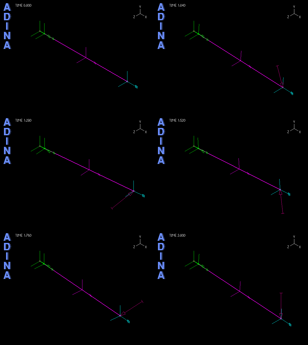
Figure 6 shows the connector element model of the assembly as it is subjected to the same time-dependent loads as the 3D solid model shown at the top of this page. Figure 7 shows the responses predicted by each model to the same time-dependent applied force.
Figure 6 Connector element model of the radius arm and attached bushings subjected to a time-dependent loading sequence. The fixed node corresponds to the anchoring point of the rear bushing. Three connector elements are used: 1) to model the rear bushing/radius arm connection (green); 2) to model the linear response of the radius arm (magenta); and 3) to model the front bushing/radius arm connection (cyan).
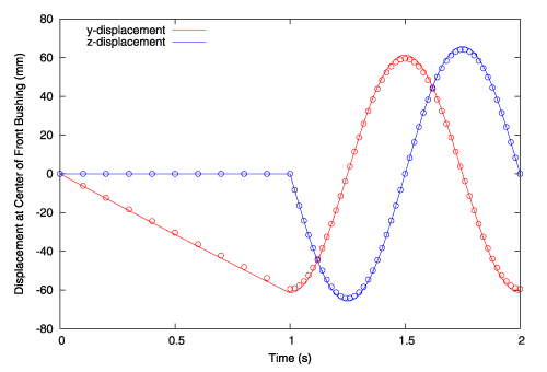
As the suspension articulates and the component undergoes finite rotations (as it would when the rear bushing bends), the connector element’s local coordinate system follows the elements and the response properly transforms. As seen, practically the same results are obtained, but the connector element model is obviously far more computationally efficient.
Conclusion
This example demonstrates how the connector element can be used to model linear or nonlinear elastic behavior. The connector element can also be used to model linear or nonlinear damping behavior. For example, coil-over shock assemblies can easily be modeled using a single nonlinear connector element possessing both stiffness and damping responses. The user may also directly specify damping matrices.
The connector element is the latest addition to ADINA’s advanced nonlinear capabilities, and its general formulation and flexibility give the user easy access to powerful and increasingly efficient modeling techniques.
Keywords:
Connector element, bushings, nonlinear structural response, element stiffness matrix, large displacements, large rotations, vehicle suspensions
