MicroStation, the only computer-aided design software purpose-built for infrastructure design, has a variety of features to help architects and engineers bring their vision to life. Here, we’ll highlight two of MicroStation’s key features – Dynamic Views and Intelligent Sheets.
Dynamic Views
This feature in MicroStation, formerly called Drawing Extraction, makes model analysis and documentation more interactive and intuitive on projects involving multidisciplinary professionals. In this CAD drawing software, static views are now replaced by the ability to create live, intelligent views of a design that updates automatically as the design evolves. MicroStation’s design intelligence makes teamwork easier while minimizing errors on project deliverables.
The features of Dynamic Views include:
Drawing Composition
Drawing Composition offers a dynamic approach for interconnecting project drawings an entire team works on simultaneously. For example, you can have one person working in the first-floor plan design file while the other works in the second-floor plan design file for the same project.
After the project design is completed, you can create a design composition that combines the individual components by referencing them into a 3D design model. To do this, first create a new design model in your design file. From there, you can reference the desired design models either from the References dialog or Explorer dialog. The design models can be from the same DGN file, or other DGN files.
Detailing Symbol Styles
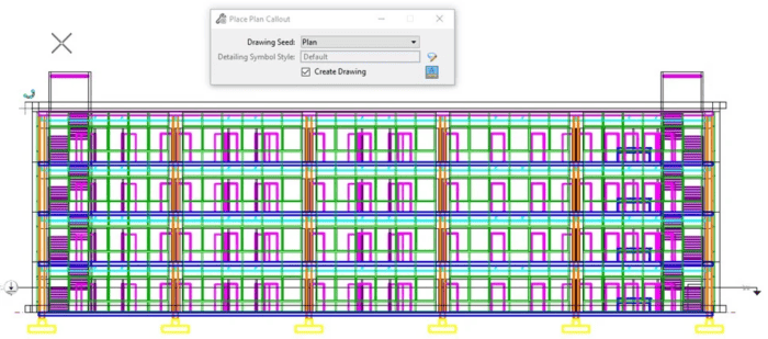
Detailing symbols are used for the placement of different types of callouts, title texts, and revision clouds. They contain fields and links that update automatically and make the models more interactive and intuitive.
The Detailing Symbol Styles option allows you to define standards for detailing symbols via symbology settings and placeholder fields. Any change in the style setting will propagate to all detailing symbols automatically. It saves your team time and keeps the project consistent.
Named Boundaries
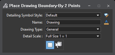
The Drawing Boundary and Named Boundary features can be very useful for automating dynamic views.
When you create multiple saved views of each part of your design with different levels turned on or off, you can place each of these views in sheet models to plot them. Using Drawing Boundaries and Named Boundaries will help you achieve this easily and efficiently.
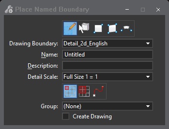
To start, use the drawing boundaries to predefine an area on a sheet model with a drawing. This can be thought of as a target location for a drawing on a sheet model. Then you can create a named boundary from a drawing boundary. Each named boundary is referenced on a drawing and sheet model. The selected drawing boundary of the sheet model contains the named boundary.
Intelligent Sheets
This feature can generate consistent, high-quality paper and digital deliverables such as paper plots, reports, 2D or 3D PDFs, and 3D physical models. Intelligent Sheets automates and speeds annotation, display styles, and reports by generating them directly from the embedded properties of objects.
The features of Intelligent Sheets include:
Sheet Indexing
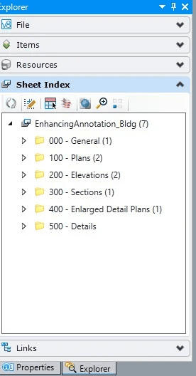
A sheet index is a centralized and structured collection of sheets in your WorkSet. Sheet indexes can be useful in creating a construction document set (also called as sheet set or construction set) that contains all the sheets of your WorkSet. You may link any sheet model from any design file of your WorkSet into a sheet index. You can then collectively manage the properties of all the sheet models within the sheet index.
Sheet Index
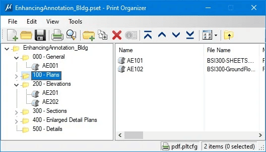
Sheet numbering rules enable you to define rules for generating sheet numbers for all sheets in the sheet index. Sheets can be organized hierarchically in folders, with the ability to override sheet numbering rules for sheets in each folder. Custom properties can be attached to sheets and placed as text fields in the sheet. Custom properties can also be attached to the folders and the sheet index. An index table for the cover sheet can also be generated from the sheet index. Sheet indexes can also be opened using the Print Organizer for printing.
Sheet Models
Sheet Models are an electronic drawing sheet that typically consists of design model references that are scaled and positioned to create a printable drawing.
Dynamic Views
As mentioned above, Dynamic Views allows automated interaction among the model analysis and documentation of several files used by different professionals.
Text Fields
Text Fields automatically numbers your sheets. It saves you time when you need to add or remove a sheet.
Print Organizer
Once you finalize the sheet index, a simple click allows you to send your index to Print Organizer to print out a complete construction set of drawings.
Smart Project Deliverables within Intelligent Sheets
Once the sheets have been produced, you can include smart features like hyperlinks to specifications and product information, automated title block information creation, and other automated annotation tasks for smarter deliverables.
The Sheet Composition stage enables you to create sheets that represent finished work, ready for publication and delivery. The automated layout can be based on scale, location, or along path. Once generated, the Sheet layouts can be modified for fine adjustments. However, many of the graphics are placed automatically and are linked as needed.
The features of Smart Deliverables include:
Named Boundary
A Named Boundary is a region that has a name and data associated with it. It is a Named Fence with the Create Drawing workflow attached. You can place a Named Boundary as you do any Fence with one addition — from Drawing Boundary.
Drawing Boundary
The Drawing Boundary consists of a boundary and an annotation. The annotation contains the text fields and a drawing line. It is always aligned to the Sheet’s bottom. Drawing Boundaries are defined in a DGNLIB (Design File Libraries) and are created, edited, and managed by CAD Administrators. The user simply chooses the type of Drawing Boundary needed at time of placement.
Labeling with Item Types
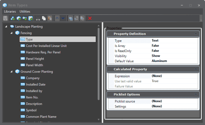
The automation of text is always welcome. With MicroStation CONNECT Edition, you can find information about a drawing and its data and represent it as text. The properties of any item can be found and reported, including values that change over time.
Adding Hyperlinks
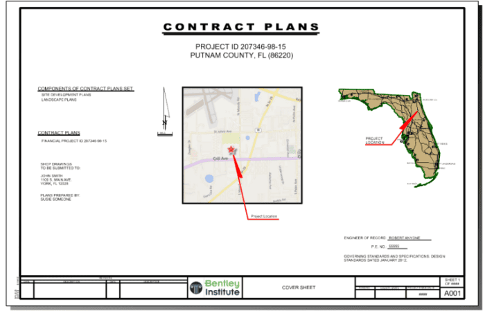
During the drawing creation process, you can automatically add hyperlinks to valuable data such as specifications, websites, or documents. The addition of hyperlinks can be done manually or through the seed model used to generate the drawing. In addition, you can add Raster images that are hyperlinked. For example, you may wish to show the area of interest as a raster image. That image not only shows the location but can be hyperlinked to a mapping service of your choice.
These features are all found in MicroStation to allow you to deliver smarter deliverables.

