AccuDraw is a remarkable MicroStation tool that boosts drawing productivity by tracking and anticipating the next drawing steps. The AccuDraw settings box appears on the MicroStation desktop when AccuDraw is active, and the AccuDraw compass appears on data points. The AccuDraw settings box makes precise coordinate entry faster and easier than the key-in approach, saving time.
Why do we need AccuDraw for 2D CAD Drawing and 3D Model Production?
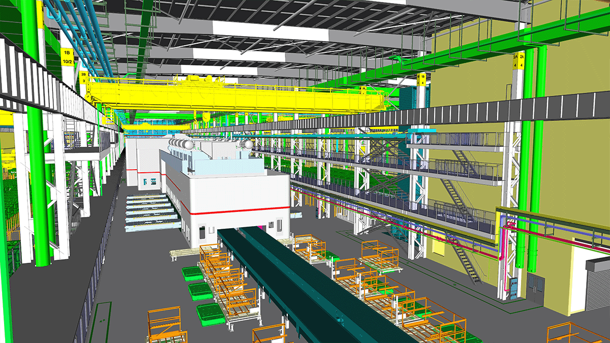
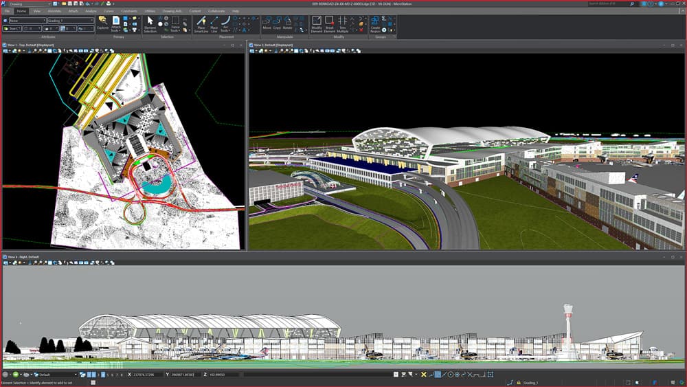
Almost all engineering projects create and use CAD data in the form of 2D drawings and 3D models. Precision and speed in this process are vital for successful and timely project delivery. Though the domain and intent of the CAD data vastly varies, its underlying geometry has the common needs of precise location, distances, and directional inputs. AccuDraw adds both precision and speed to the input process and offers ease of navigation in 2D and 3D space. Additionally, it provides handy access to many other tools, settings, and functionalities.
How does AccuDraw help?
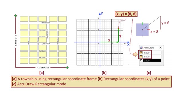
AccuDraw has a dynamic coordinate system with an origin at the right place and an axis pointing in the direction you want to draw. Rectangular and polar coordinate systems are included in the AccuDraw drawing plane for locating points. The coordinate systems are identical to those provided by the precision key-in tools, except that all values displayed in the AccuDraw coordinate systems are derived from the AccuDraw compass origin, not the design plane’s origin point.
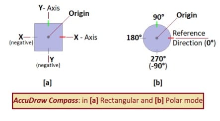
The rectangular coordinate system has X and Y variables that show the pointer’s rectangular offset from the compass center.
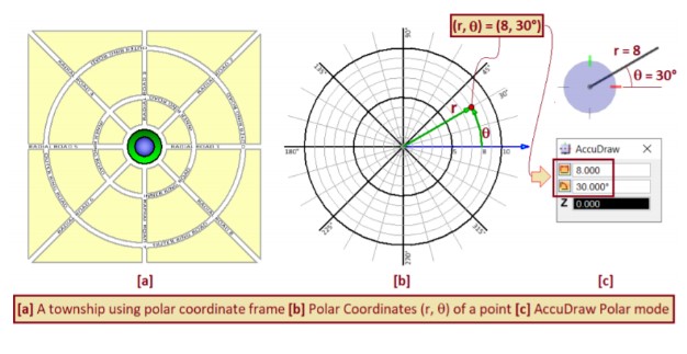
Fields in the polar coordinate system display the pointer’s distance and rotation from the compass center. The distance field is represented by a linear dimension icon, whereas an angular dimension icon represents the angle field.
AccuDraw has Two Main Components
AccuDraw Compass visually depicts the current coordinate frame that AccuDraw is using in the design file. It shows its location (origin), orientation (reference axes), and the plane defined by them. The shape of the compass indicates the mode, as shown.
 The AccuDraw Coordinate Window provides two-way communication for input as well as output. The coordinate window helps in displaying coordinates numerically. It also accepts inputs – distances, angles, etc., along with short, alphanumeric key-ins called AccuDraw Shortcuts.
AccuDraw brings a lot of power and freedom of creating geometry in any location, orientation, and plane in the design space. Precise numerical inputs and convenient access to MicroStation tool settings and functionalities add to the precision and efficiency. Where we could share few capabilities, but AccuDraw has a lot more to offer still!
The MicroStation Help gives you the details on all the described functions. You can access the following link to learn more about the AccuDraw tools View Learning Path.