ADINA is known for its powerful capabilities in the solution of fluid structure interaction (FSI) problems. For many years, ADINA FSI solutions have been used successfully for many applications in a wide range of industries.
 Although ADINA FSI is a powerful tool for many problems involving structures and fluid flow, there are certain classes of problems involving structures and fluids that do not require the use of ADINA FSI but can be solved effectively through a purely structural analysis. An example of such problems is the analysis of fluid-filled cavities inside a solid or structure. In this Tech Brief, we demonstrate the use of the hydrostatic fluid feature in ADINA Structures that can be used to model the pressure and volume variation in cavities filled with compressible fluids. An example of such application is the simulation of a compressed fluid-filled rubber capsule as shown in the animation above.
For the hydrostatic fluid model, it is assumed that the fluid pressure in the cavity is uniform at any point of time. The model only requires the hydrostatic fluid pressure to be applied on the internal surface of the cavity, with no material definition required. The variation of the hydrostatic fluid pressure and the volume of the cavity is governed by the ideal gas law below.
Although ADINA FSI is a powerful tool for many problems involving structures and fluid flow, there are certain classes of problems involving structures and fluids that do not require the use of ADINA FSI but can be solved effectively through a purely structural analysis. An example of such problems is the analysis of fluid-filled cavities inside a solid or structure. In this Tech Brief, we demonstrate the use of the hydrostatic fluid feature in ADINA Structures that can be used to model the pressure and volume variation in cavities filled with compressible fluids. An example of such application is the simulation of a compressed fluid-filled rubber capsule as shown in the animation above.
For the hydrostatic fluid model, it is assumed that the fluid pressure in the cavity is uniform at any point of time. The model only requires the hydrostatic fluid pressure to be applied on the internal surface of the cavity, with no material definition required. The variation of the hydrostatic fluid pressure and the volume of the cavity is governed by the ideal gas law below.
 By default, the ambient pressure is zero which corresponds to the ideal situation when there is no environmental pressure. In the real world however, the ambient pressure is usually nonzero, and in most case it is the atmospheric pressure. Although a nonzero ambient pressure does not directly act on the model, it can dramatically affect the value of the gauge pressure.
The example below illustrates a benchmark solution of the hydrostatic pressure inside a rectangular space enclosed by six surrounding faces as shown in Figure 1. The top and bottom blocks are meshed with solid elements while the four vertical sides are dummy segments without elements used to form the enclosed volume. Hydrostatic pressure is applied on all six inside faces of the enclosed space. A prescribed displacement is applied on the top block to compress the enclosed space to the half of its original volume.
By default, the ambient pressure is zero which corresponds to the ideal situation when there is no environmental pressure. In the real world however, the ambient pressure is usually nonzero, and in most case it is the atmospheric pressure. Although a nonzero ambient pressure does not directly act on the model, it can dramatically affect the value of the gauge pressure.
The example below illustrates a benchmark solution of the hydrostatic pressure inside a rectangular space enclosed by six surrounding faces as shown in Figure 1. The top and bottom blocks are meshed with solid elements while the four vertical sides are dummy segments without elements used to form the enclosed volume. Hydrostatic pressure is applied on all six inside faces of the enclosed space. A prescribed displacement is applied on the top block to compress the enclosed space to the half of its original volume.
 is gradually increased from 0 to 1000; then in the second stage, t = 1 to 2, the space is compressed to half the original size. Two different cases, with and without ambient pressure, are separately considered. In the case with non-zero ambient pressure, the ambient pressure
  also takes the value 1000. The variation of the calculated hydrostatic fluid pressure (gauge pressure) with time for both cases is shown in the video of Figure 2 below. The calculated solutions correspond exactly to the analytical solutions.
 Although ADINA FSI is a powerful tool for many problems involving structures and fluid flow, there are certain classes of problems involving structures and fluids that do not require the use of ADINA FSI but can be solved effectively through a purely structural analysis. An example of such problems is the analysis of fluid-filled cavities inside a solid or structure. In this Tech Brief, we demonstrate the use of the hydrostatic fluid feature in ADINA Structures that can be used to model the pressure and volume variation in cavities filled with compressible fluids. An example of such application is the simulation of a compressed fluid-filled rubber capsule as shown in the animation above.
For the hydrostatic fluid model, it is assumed that the fluid pressure in the cavity is uniform at any point of time. The model only requires the hydrostatic fluid pressure to be applied on the internal surface of the cavity, with no material definition required. The variation of the hydrostatic fluid pressure and the volume of the cavity is governed by the ideal gas law below.
Although ADINA FSI is a powerful tool for many problems involving structures and fluid flow, there are certain classes of problems involving structures and fluids that do not require the use of ADINA FSI but can be solved effectively through a purely structural analysis. An example of such problems is the analysis of fluid-filled cavities inside a solid or structure. In this Tech Brief, we demonstrate the use of the hydrostatic fluid feature in ADINA Structures that can be used to model the pressure and volume variation in cavities filled with compressible fluids. An example of such application is the simulation of a compressed fluid-filled rubber capsule as shown in the animation above.
For the hydrostatic fluid model, it is assumed that the fluid pressure in the cavity is uniform at any point of time. The model only requires the hydrostatic fluid pressure to be applied on the internal surface of the cavity, with no material definition required. The variation of the hydrostatic fluid pressure and the volume of the cavity is governed by the ideal gas law below.
 By default, the ambient pressure is zero which corresponds to the ideal situation when there is no environmental pressure. In the real world however, the ambient pressure is usually nonzero, and in most case it is the atmospheric pressure. Although a nonzero ambient pressure does not directly act on the model, it can dramatically affect the value of the gauge pressure.
The example below illustrates a benchmark solution of the hydrostatic pressure inside a rectangular space enclosed by six surrounding faces as shown in Figure 1. The top and bottom blocks are meshed with solid elements while the four vertical sides are dummy segments without elements used to form the enclosed volume. Hydrostatic pressure is applied on all six inside faces of the enclosed space. A prescribed displacement is applied on the top block to compress the enclosed space to the half of its original volume.
By default, the ambient pressure is zero which corresponds to the ideal situation when there is no environmental pressure. In the real world however, the ambient pressure is usually nonzero, and in most case it is the atmospheric pressure. Although a nonzero ambient pressure does not directly act on the model, it can dramatically affect the value of the gauge pressure.
The example below illustrates a benchmark solution of the hydrostatic pressure inside a rectangular space enclosed by six surrounding faces as shown in Figure 1. The top and bottom blocks are meshed with solid elements while the four vertical sides are dummy segments without elements used to form the enclosed volume. Hydrostatic pressure is applied on all six inside faces of the enclosed space. A prescribed displacement is applied on the top block to compress the enclosed space to the half of its original volume.
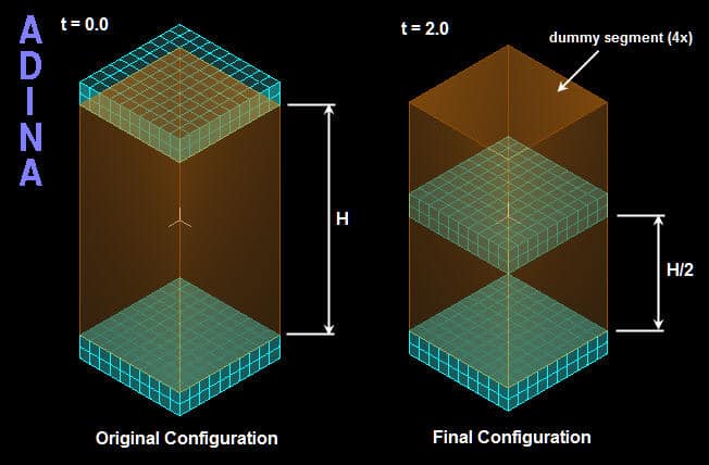 Figure 1
 Figure 2
 Figure 3
 Figure 4
- The analysis of fluid-filled cavities inside a solid or structure, where the fluid pressure in the cavity is assumed to be uniform at any point of time.
- The analysis of inviscid, irrotational fluids with no heat transfer.
- The modeling of hydrodynamic forces (e.g. the use of Morison’s equation) in the analysis of offshore structures.