Hydroelectric power plants are used for economic and environmentally friendly electric power generation all around the world. One of the technical challenges in the design of such structures is to consider the fluid-structure interaction effects. For example, when the water pressure fluctuates as it passes through the fluid passage and the hydraulic turbine, it creates a pulsatile loading that causes vibration of the powerhouse structure.
 Displacement (magnified)
In this blog post, we present some results of a study dealing with the vibrations of a powerhouse structure due to the fluid-structure interaction, obtained using ADINA. Figure 1 depicts a schematic of the powerhouse structure, the fluid passage, and the turbine. Figure 2 shows the finite element model of the coupled system. The nonlinear transient response of the coupled system was solved using 3000 implicit integration time steps, with a time step of 0.002 seconds (see Ref).
The fluid was modeled as a Navier-Stokes fluid. The turbulent behavior of the fluid was modeled using the shear stress transport (SST) model. The sliding mesh boundary condition was used to incorporate the large rotations of the turbine blades.
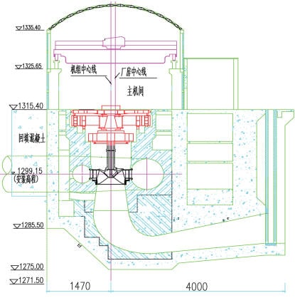 Figure 1: Schematic of the powerhouse
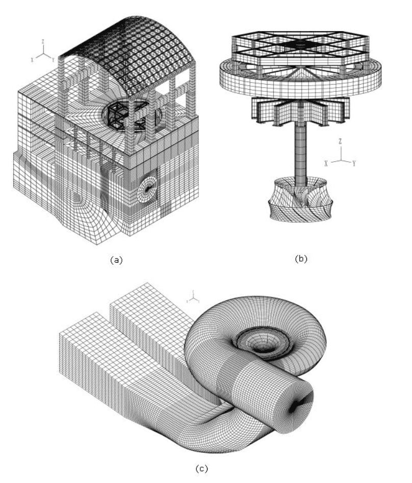 Figure 2: Finite element mesh of the (a) powerhouse structure (b) turbine) (c) fluid
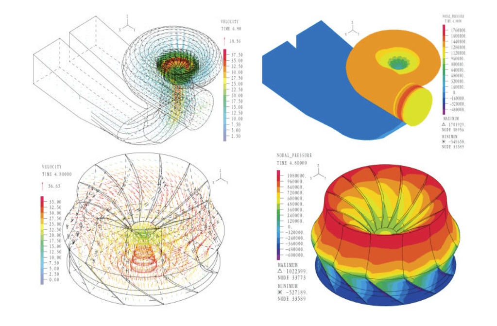 Figure 3: Velocity vector plots (left) and nodal pressure contour plots (right) in the fluid at t = 4.80 s
Figure 3 shows velocity vector and pressure contour plots in the fluid model at the time = 4.80 s.
The movies at the top show the z-displacement contour plot of the powerhouse structure, and its time-dependent deformed shape due to the pressure loading from the fluid.
The movie below shows the contour plot of the pressure in the fluid.
This case study shows some of the powerful capabilities of ADINA for solving practical fluid-structure interaction problems.