Numerical analysis is a valuable tool to support the decision-making process in geotechnical design. Such analyses might still remain excessively time-consuming if FE models are not being set up properly, if possible convergence issues cannot be quickly identified and, should they arise, if they cannot be efficiently troubleshot. This article provides a set of recommendations on the various ways you can speed up calculation time and make an even better return on your FEA investment.
Optimize your mesh
Calculation time in PLAXIS is directly related to the mesh size. The more elements a mesh contains, the larger the stiffness matrix of the system (that needs to be inverted) and the longer the calculation time will be. It is therefore very important to define the optimal model dimension and even more crucial to introduce an appropriate level of mesh refinement, and only where it really matters.
The first recommendation one could provide is to model and mesh only what is necessary. For instance, always start by identifying symmetry conditions and make use of them (this could be plane symmetry for excavation, cyclic symmetry for quay wall, etc.). In this manner, you could significantly reduce the number of elements and, consequently, associated calculation time.
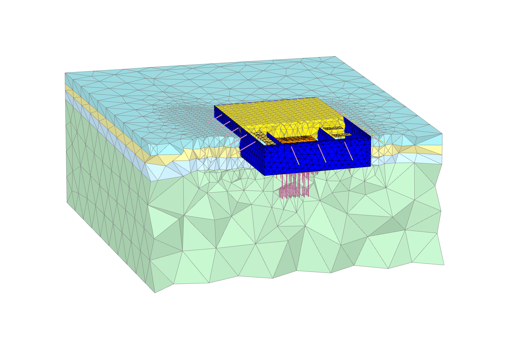
Mesh needs to be refined only in areas where large stress gradients are expected to develop. Typically, finer mesh density is required close to structures and can grow coarser moving toward the model boundaries where element size could be significantly larger. Mesh refinement zones can be advantageously defined by sets of surfaces enclosing the soil area, the mesh of which could be refined. This way, you can limit the volume over which mesh is refined.
Figure 1: Mesh refinement example
Understanding convergence behavior
Calculation progress window
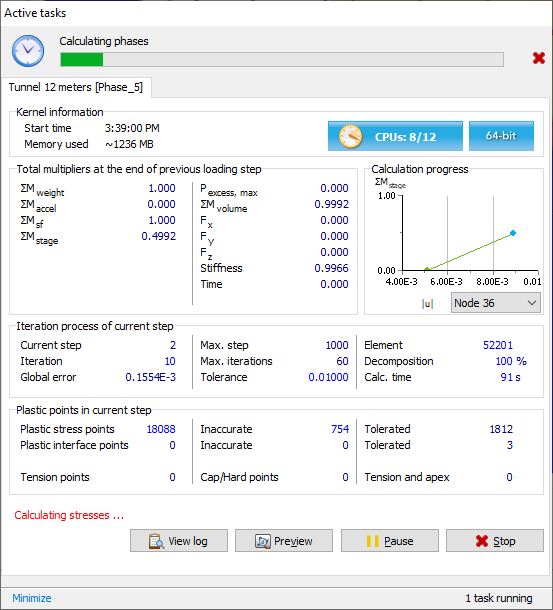
The calculation progress window as shown in Figure 2 provides a handful of interesting information pieces to be considered when evaluating the convergence rate of a given calculation. It will help users identify any convergence issues that could result in excessively long calculation time before the calculation kernel could even determine that reaching full convergence cannot possibly be reached. The key items in the calculation progress window are:
- ΣMstage: This translates the proportion of the initially applied load (at the beginning of the phase), referred to as the external forces which have been balanced by the development of soil stresses that are considered being the internal forces. At the beginning of the phase, ΣMstage =0, whereas a fully completed phase will correspond to the situation ΣMstage =1. Carefully monitoring ΣMstage offers a clear evaluation of the convergence rate for any staged construction phase. A relatively steady (or even decreasing) ΣMstage over multiple successive steps might be an indication of some convergence issues that should be further investigated by looking either in the Output results preview or the convergence log file.
- Stiffness parameter: Often referred to as the CSP parameter, this is the ratio of the (elastic) strain energy over the work done by all applied forces on the soil model. If the soil would behave elastically (which it usually would not), the CSP would be equal to 1. As irreversible strain starts developing in the soil mass (plastic or viscous strain for instance), necessarily leading to some energy dissipation, the CSP value will progressively decrease. Too low of a CSP value (1E-3 is often considered critical, as a simple rule of thumb) indicates a situation close to failure, possibly the reason for a slow convergence process and excessively large calculation time.
- Global error: This is the main quantity calculated to evaluate whether the iterative process associated with the resolution of the non-linear set of discretized equations should be stopped. It is not the only criteria, but surely one of the most important. It represents the “Euclidian” norm of the out-of-balance force vector (so, external force minus the internal force) over the norm of the initial unbalance at the beginning of the step (step being the subdivision of the phase). If the global error is larger than the tolerated one, PLAXIS will keep on iterating. For this reason, the evolution of the global error over a calculated phase is also a good indication of the convergence rate.
- Inaccurate plastic points: These are used to judge the accuracy of the solution from a local perspective (in addition to the global error, which assesses the solution accuracy from a global perspective). In a PLAXIS calculation, the number of inaccurate plastic points should be less than 10% of the total number of plastic points. Without this condition also satisfied, the iterative process will continue.
Figure 2: Calculation progress window
Convergence log files
The PLAXIS calculation kernel provides access to a log file to help you understand the convergence behavior of your analysis and debug the model if necessary. The file includes a summary of all convergence criteria for each step, attempt, and iteration of a given phase analysis. This diagnostic information is saved automatically for every analysis being run. If an analysis takes longer than expected or terminates prematurely, you can view the logging information in any editor to help determine the cause(s) and to identify ways to correct the model accordingly.
Running multiple independent calculation phases simultaneously
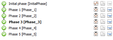
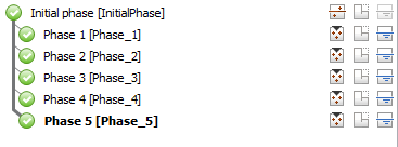
Many PLAXIS calculation projects are composed of multiple independent phases, often introduced for the analysis of multiple scenarios from a common construction history (as shown in Figure 3b). By default, any PLAXIS calculation phase will dedicate all available calculation cores of the machine for each phase, irrespective of their level of interdependency.
Figure 3a: Dependent
Figure 3b: Independent
However, by assuming just one single core to each calculation phase, independent phases can be run simultaneously on the same calculation machine. This saves you a considerable amount of time compared to having to run them all in a series.
Solver types for PLAXIS 3D Calculation
PLAXIS 3D offer two types of solvers:
- PICOS iterative solver (default solver)
- PARDISO direct solver
For the majority of geotechnical problems, the PICOS iterative solver is the most efficient, which explains why this is the solver that PLAXIS 3D calculation opts for by default.
The main advantage of the iterative solver is its memory usage, which is significantly less than a direct solver for the same sized problems. For well-conditioned problems, it converges also considerably faster compared to a direct solver, with a time gain increasing as the number of elements grows larger.
However, for geotechnical problems and for not well-conditioned problems (for instance, an extremely large difference of stiffnesses in stress analyses or permeabilities values in flow or consolidation problems), the PARDISO direct solver usually performs better and therefore faster compared to PICOS. The PARDISO solver will require a substantially larger amount of memory (considerably more than the PICOS solver would), but will provide faster solutions for such not well-conditioned problems.
Learn more about this event here.
Discover the PLAXIS Productivity Strategies series featuring blogs, LinkedIn Live sessions, and webinars.
Learn the top efficiency tips to solve your common problems.
Learn more about PLAXIS with Bentley’s eStore:
Check out the Concept to Construction series including the PLAXIS session here.
Interested in PLAXIS soil models? Find more resources here.
Get access to new educational PLAXIS videos to explore the benefits and value of using PLAXIS.
For the price and the amount of Keys included in PLAXIS Virtuoso Subscription, please visit this page.
Want to learn more about what PLAXIS can do for you? Don’t hesitate to contact our geotechnical experts. We are happy to help.

