This blog is a part of the series Tunnel your way to success with PLAXIS.
Introduction
This is the second blog covering the modelling of the Traditional Method of Madrid in PLAXIS 2D and 3D. For further details on the method, please refer to the webinar (Traditional Tunnelling Method: Application of MTM with PLAXIS 2D/3D) and blog 1 (PLAXIS 2D – Traditional Tunnelling Method: Application of MTM). In this paper a 3D Approach to Madrid Traditional Method will be presented. However, a 3D model is not always possible due to project constraints, such as budget and deadlines. This paper aims, firstly, to enhance the current design approaches, via a new 2D approach based on a calibration with a 3D SSI model; secondly, to contribute for a more informed design when a 3D model is not available; and thirdly, to contribute to more sustainable designs without compromising safety and quality.
SOIL-STRUCTURE INTERACTION Models
Firstly, it is necessary to create two models: a three-dimensional and a two-dimensional SSI model, based on the first one. To generate both models, the finite element calculation programme PLAXIS 3D and 2D were used, respectively. The geology for both models is covered in Blog 1 and is summarised in the table below.
Table 1: Summary of the stratigraphy of the models
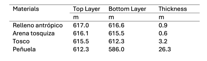
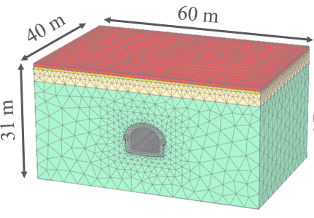
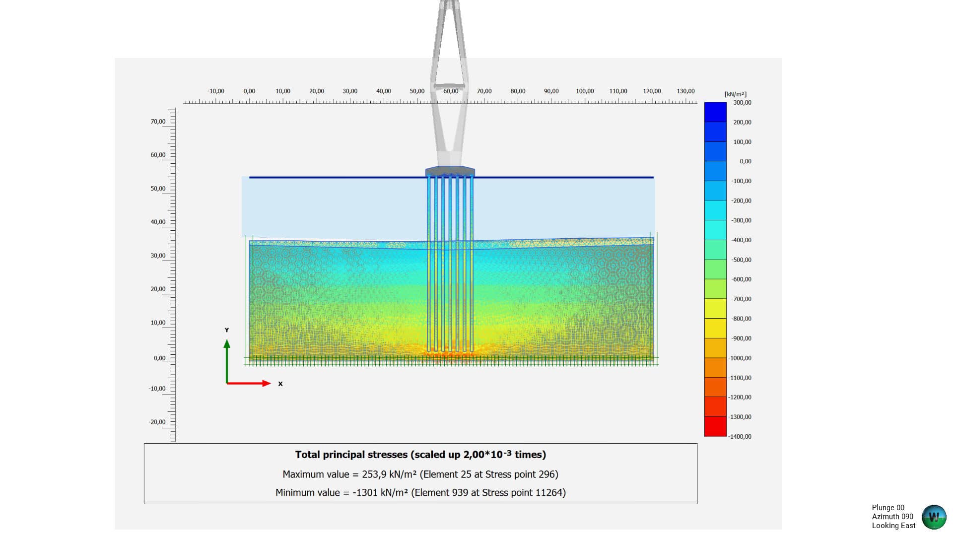
Figure 2: 3D SSI Model
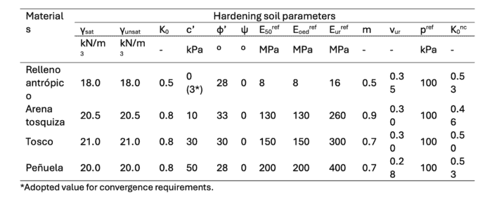
The ground constitutive models are also presented in Blog 1 and summarised in the table below.
Table 2: Hardening soil ground parameters
3D SSI Model
The three-dimensional Soil Structure Interaction (SSI) model developed in PLAXIS 3D comprises the dimensions of 40 by 60 meters in plan, by 31 meters deep and can be seen on the previous image. The model has over 162000 elements and the tunnel liner is modelled as volumetric elements with dummy plates at its centroids, to facilitate the extraction of internal forces for structural design. The following images show in more detail the volumetric elements used for modelling the unreinforced concrete liner and the structural elements modelled used for this 3D SSI model, such as: the waler steel beams, timber planks, and timber struts to model the temporary works that support the ground prior to the installation of the concrete permanent liner.
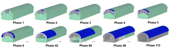
Finally, the model replicates the complex sequence of Madrid’s traditional Method and has six independent phases to excavate one single crown advance with a 2.5 m round length. In total the model represents the construction of 16 round lengths (16*2.5 = 40 m), and its walls and invert installation, thus comprising a total of 115 phases.
Calibration
The aim of the calibration is to obtain a set of calculation phases that accurately represent the behaviour of the Traditional Method of Madrid with a required three-dimensional behaviour for a two-dimensional analysis. This fact implies a simplification of the calculation models since the problem will be analysed as a plane strain in 2D. This simplification implies that the phases of the construction process cannot be conveniently idealised directly, but that a study based on a three-dimensional model is necessary to be able to represent the real effect of the whole excavation and support process. To be able to correctly represent the actual behaviour in a 2D model, a calibration of the confinement effect experienced in 3D models must be carried out. This calibration is carried out using the PLAXIS numerical parameter Mstage which controls the degree of deconfinement of the excavations; in other words, the ratio of unbalanced stresses that must reach equilibrium at the one stage of the model.
Therefore, the main variable of this analysis has been the level of relaxation that the ground may experience in each calculation phase when it involved an excavation. In addition, some assumptions have been made based on experience and knowledge of the construction method. Firstly, a virtual support phase has been created to simulate the behaviour experienced by the soil when excavating the top heading, since without this phase the deformations achieved in the three-dimensional model would not be reached in the same way, due to distance to the excavation face and longitudinal ground arching effect. Secondly, it has been imposed that the level of relaxation when excavating the lateral benches are equal to guarantee the symmetry of the model. The calibration process has been carried out by comparing the level of ground surface subsidence and the crown vertical movements in each calculation stage for each model. After obtaining accurate deformation results, it has been verified that the forces experienced in the tunnel structure are comparable in both models. The results obtained are presented in the following sections.
Ground settlements
The maximum value of the surface settlements in the final phase of the calculation are: for the 3D case the maximum settlement is equal to 7.74 mm, while for the 2D case it is equal to 7.73 mm. Regarding the variation of these vertical movements throughout the calculation phases, it can be seen in the following graphs how the settlement obtained in the first phase, which is the most critical, represents approximately 40% of the final value reached in both models, specifically 41% for the 3D model and 42% for the 2D; for both cases implies a settlement equal to 3.2 mm. Then, in the concreting phase of the crown, the accumulated settlements are equal to 72% in both cases, which represents a settlement equal to 5.6 mm. In the phase of excavation of the left wall, the accumulated value amounts to 91% (7.1 mm) for the 3D case and 88% (6.8 mm) for the 2D case. After the excavation and concreting phase of the right wall, the acquired values of accumulated settlements exceed 95% in both models, see Figure 7.
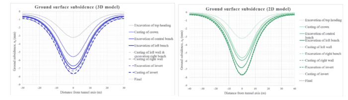
Figure 5: Ground surface subsidence of the models at each calculation stage
As far as the vertical movements of the tunnel crown are concerned, the value achieved in the final phase is equal to 10.7 mm for the 3D case and 10.4 mm for the 2D case (see Figure 8). The maximum vertical is correctly adjusted in the phase of the excavation of the top heading (5.2 mm for the 3D and 4.7 mm for the 2D). In the phase of crown casting, the maximum settlement obtained in the 3D model is equal to 5.4 mm and in the 2D case it is equal to 8.1 mm. This difference between the values of the vertical movements is progressively reduced in the following phases: in the phase of excavation of the left bench the result obtained is equal to 10 mm, while in the 2D case it is equal to 9.4 mm; in the phase in which the invert is excavated it is equal to 10.6 mm in the 3D model and 10.4 mm in the 2D model, until finally arriving at a difference of less than 0.3 mm.
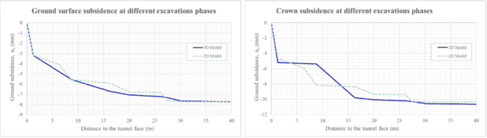
Figure 6: Ground surface subsidence of the models at each calculation stage
Tunnel liner internal forces
The forces obtained in the tunnel lining have been analysed in the final phase of the calculation, i.e., when the section is completed with a 7-day concrete in the entire tunnel lining. The following graph shows the maximum and minimum values for the stresses in the crown and the side walls.
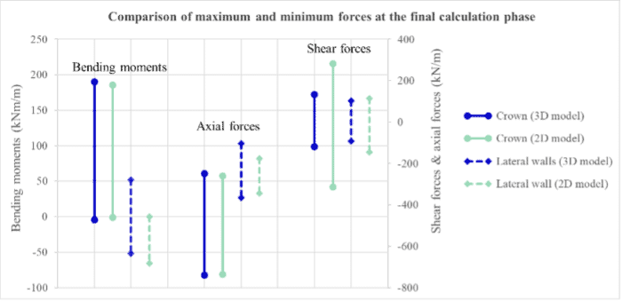
Figure 7: Maximum and minimum forces in each model at the last calculation phase
Results discussion
Firstly, the settlements obtained on the surface are practically equal in the last phase of the calculation, this point is evidenced by the fact that the relative error is equal to 0.13%. On the other hand, the calibration reached in the first calculations phases is also well adjusted, the relative error at this stage is less than 1%. From the concreting of the right sidewall onwards, the variation of the surface settlements is practically negligible, and the relative error does not exceed 1%. In general, the surface subsidence adjustment is very accurate in all the calculation phases analysed. Secondly, the vertical movements in the tunnel crown are well adjusted in the first phase and from the concreting of right sidewall stage until the end of the construction procedure. At the end stage, the relative error is equal to 2.8%, which means a difference of 0.3 mm. The evolution of these movements shows a slightly different behaviour in the intermediate phases. Lastly, the forces in the final phase of the model are relatively well adjusted, in the tunnel crown where the maximum absolute error for each force is: 4.5 kNm/m for the bending moments, 11.6 kN/m for the axial forces and 148 kN/m for the shear ones. Although in the case of shear stresses the error is higher, this only indicates the maximum value and, in any case, the shear force does not typically drive the design due to the significant thickness of the concrete liner. On the other hand, in the case of the side walls the fitting is not as accurate as for the crown, the absolute errors obtained are: 52 kNm/m for the bending moments, 72 kN/m for the axial forces and 54 kN/m for the shear forces. This fact may be due to the construction sequence simulation, since the main difference between both models is the excavation of the lateral benches, since while in the two-dimensional model each wall is excavated and concreted in different phases (4 phases in total), in the three-dimensional model the excavation of one wall is staggered with the concreting of the other. Despite this, the obtained adjustment is considered suitable for the analysis.