In today’s world of modern and exotic engineering materials, it is easy to overlook the importance of inexpensive yet extremely useful materials such as gray cast iron. Some of the reasons for cast iron’s continued use in industry include its compressive strength, corrosion resistance, machinability, and structural rigidity. Cast iron also has excellent damping capacity, which is useful in applications involving high frequency vibrations such as bearing and gearbox housings. We demonstrate ADINA’s cast iron modeling capabilities by investigating the stress distributions within a cast iron pillow block bearing housing under service loads.
 Modeling Challenges
Gray cast iron is more brittle in tension than most metals. This brittleness is attributed to the microstructure of the material, which consists of a distribution of graphite flakes in a steel matrix. In tension the graphite flakes act as stress concentrators, leading to an overall decrease in mechanical properties (such as yield strength). In compression, on the other hand, the graphite flakes serve to transmit stresses, and the overall response is governed by the response of the steel matrix.
The above characteristics manifest themselves in the following macroscopic properties:
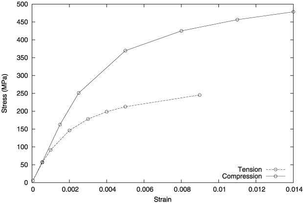
- Different yield strengths in tension and compression, with the yield stress in compression being three (or more) times the yield stress in tension.
- Inelastic volume change in tension, but little or no inelastic volume change in compression.
- Different hardening behavior in tension and compression.
Figure 1 shows a typical compressive and tensile stress/strain curves for cast iron.
It is commonly accepted that a Mises-type yield condition along with an associated flow rule models the material response sufficiently accurately under compressive loading conditions. This assumption is not true for tensile loading conditions. A pressure-dependent yield surface with non-associated flow is required to model the brittle behavior in tension, such that the cast iron material model has a nonsymmetric constitutive tensor, see refs. [1] and [2].
In ADINA, the user inputs separate stress/strain curves for tension and compression. These responses can also vary as a function of temperature for thermomechanical analyses. ADINA offers the ability to accurately and reliably model the thermomechanical response of cast iron by using a composite yield criterion consisting of a Rankine surface in tension and the von Mises cylinder in compression. ADINA also allows users to predict failure using the modified Mohr-Coulomb criterion.
Under general loading conditions, the cast iron material has a nonsymmetric constitutive tensor, thus the material model also takes advantage of ADINA’s powerful nonsymmetric sparse solver. Also, although plastic motions in cast iron are volume-preserving (isochoric) under compression, they are not volume-preserving under tension. The cast iron model is best used with ADINA’s mixed displacement-pressure (u/p) element formulation. The u/p formulation and nonsymmetric sparse solver yield excellent rates of convergence.
Pillow Block Bearing
Here we can see a pillow block bearing housing (green) with the steel bearing race (orange). The loads are applied through a steel bearing race pressed into place with contact conditions.
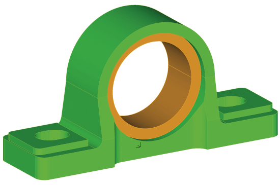
Under service, the loads can change directions; e.g., while supporting conveyors. The modeling of contact between the housing and the bearing includes a press-fit with an interference of 0.01 mm.
This model can be used to determine the stress and safety factor distributions (using the modified Mohr Coulomb criterion) and the contact state between the bearing race and the housing.
Modeling Approach
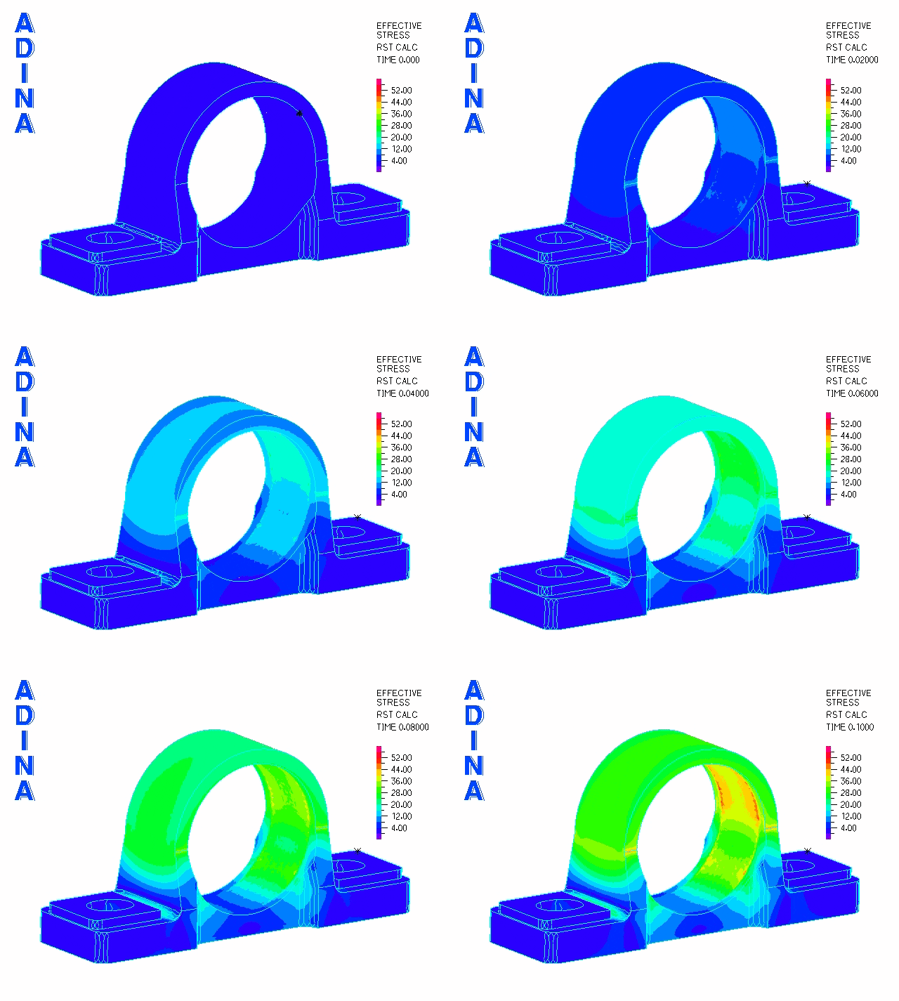
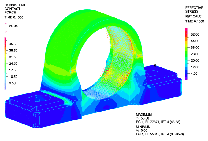
The press fit is modeled using the gap-override feature of ADINA’s contact algorithm. This feature allows the user to easily define interference fits. The bearing race is modeled as steel and positioned within the bearing housing with an interference of 0.01mm. Below, we can see the stresses after the bearing race has been press-fit into place before any other loads are applied.
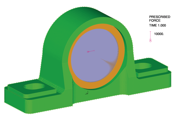
The second phase is modeled using a restart analysis following the fitting of the bearing into position. To simulate service loading conditions, we apply a transverse load through the bearing via a rigid link spider. These loads (originating from a shaft) are transmitted to the cast iron bearing housing.
Failure Criteria
Although it is of course possible to plot stresses in the loaded bearing, in this case, it is more interesting to visualize the safety factor distribution.
Using ADINA’s cast iron model, brittle failure under multiaxial loading can be predicted using the modified Mohr Coulomb criterion. This is appropriate for brittle fracture. This feature allows the user to easily identify the local regions of the cast iron housing which are approaching failure. To use this feature, the user inputs the ultimate tensile and compressive strengths, along with a safety factor.
Failure is governed by the maximum principal stress and the minimum principal stress
. These stresses are compared against the user-supplied ultimate strengths in compression and tension
and
.
The user-defined safety factor n is the amount by which the stresses can be increased before the failure criterion is reached. Graphically, each safety factor n corresponds to a curve in the plane, as shown below.
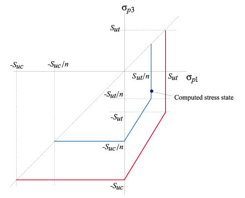
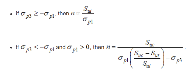
The computed safety factor is calculated as follows:
When using the cast-iron model’s modified Mohr failure criterion, ADINA can plot both the computed safety factor and the safety factor difference (that is, the difference between the user-input safety factor and the computed safety factor).
Below, we see the safety factor difference distribution within the cast iron housing with the service load applied.
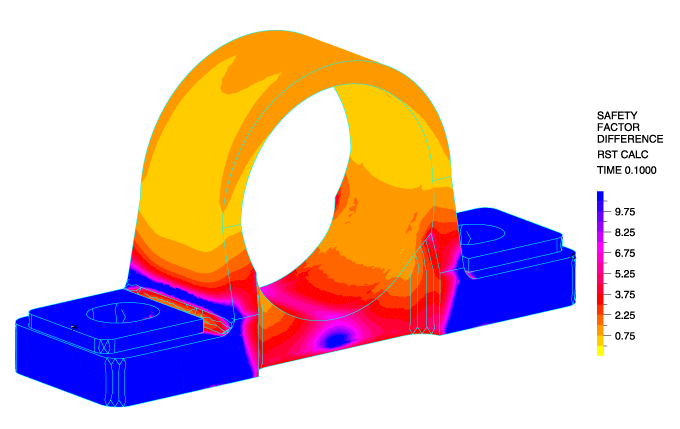
This feature allows for convenient cast iron failure analysis directly within ADINA’s post-processing environment.
This material model can be used with the 2-D solid plane strain, 2-D solid axisymmetric, and 3-D solid elements. The cast iron material can be used with the small displacement/small strain, large displacement/small strain and large displacement/large strain formulations.
Conclusion
ADINA’s powerful cast iron material model can be used for accurate and reliable failure analysis of gray cast iron. This material model takes full advantage of ADINA’s other advanced features such as its mixed (u/p) formulation and nonsymmetric sparse solver, ensuring outstanding convergence performance.
Keywords:
Gray cast iron, mixed (u/p) formulation, nonsymmetric sparse solver, non-associated flow, bearing housing, contact, interference fit
References
- L. F. Coffin, “The Flow and Fracture of a Brittle Material,” J. Appl. Mech., 1950, Vol. 72, pp. 233–248
- J. E. Shigley, Mechanical Engineering Design, 3rd edition, McGraw-Hill, 1977, Section 5.8
