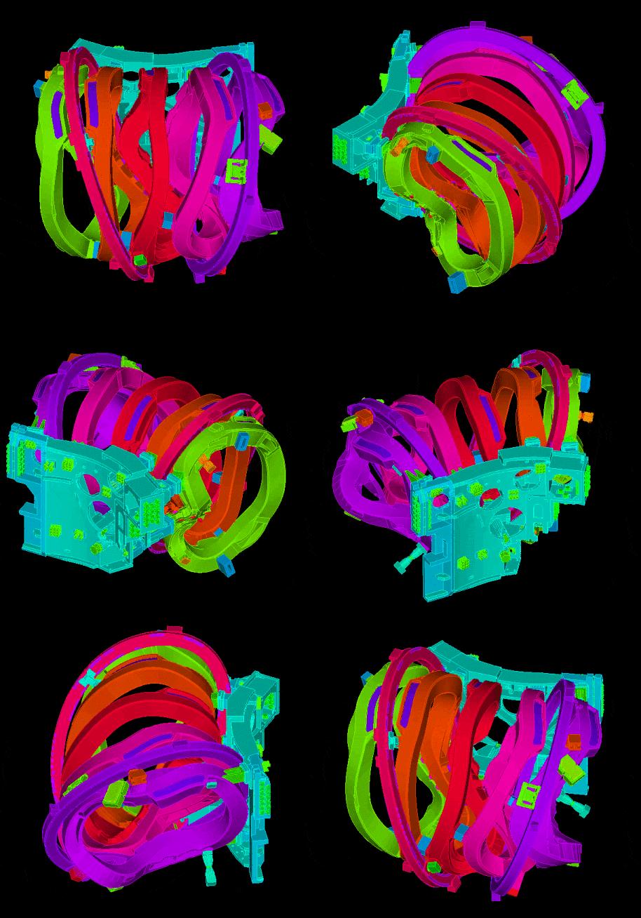
In a previous Brief, we presented some structural analysis results of the superconducting coil of the Wendelstein 7-X, the world’s largest plasma fusion experimental device of the stellarator family.
In this Brief, we present another aspect of this long-term R&D project. We focus on the connection of the coil to its support structure (see Ref.).
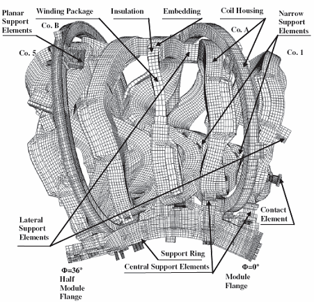
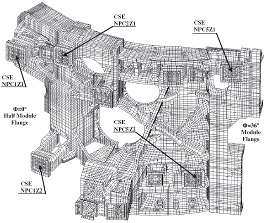
Portions of the coil and the support structure are shown in Figures 1 to 3 and the movie above. Due to the symmetry of the geometry and loading, only 1/10th of the total structure is modeled. Special symmetry boundary conditions are applied to the boundaries using the constraint equations available in ADINA. The model mainly consists of 3D solid elements. Also, a number of beam elements are used to model bolts.
The structure is subjected to electromagnetic forces, caused by the current in the superconducting coils, and loading due to the pre-tensioned bolts.
The model consists of about 6 million DOFs, more than 120,000 contact segments and about 950 bolts.
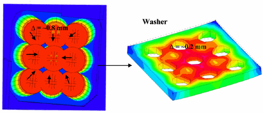
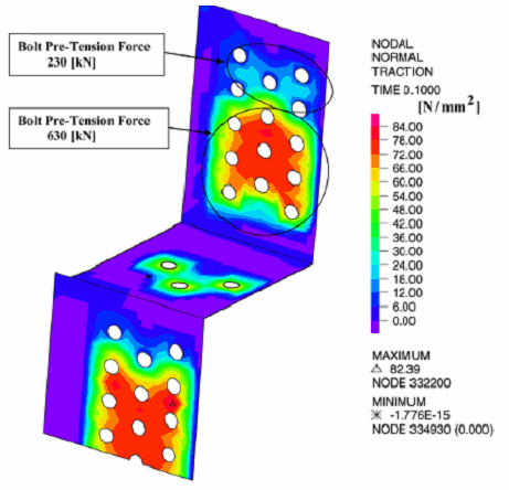
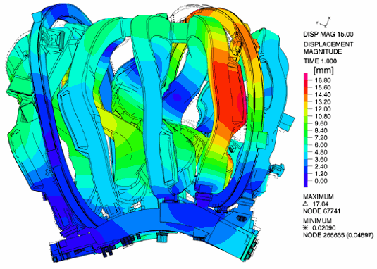
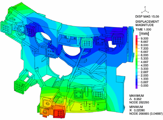
The analysis was performed in two steps. In the first step, the bolts were tightened; here the bolt forces were gradually increased to their final values. Then, in the second step, the electromagnetic forces were applied. Figures 4 and 5 show results for the bolt-tightening step, while Figures 6 and 7 show the deformations after the electromagnetic forces were applied.
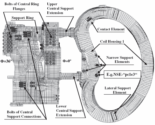
Figure 2 Finite element model of the superconducting coil
Figure 3 Finite element model of the support structure
Figure 4 Displacement contour plot of bolt heads and washer due to the bolt tightening
Figure 5 Contact normal tractions at the center of the support ring after the bolt tightening
Figure 6 Displacement contour plot (coil)
Figure 7 Displacement contour plot (support structure)
Bolted assemblies are abundantly used in many industrial applications (e.g., engine blocks, axles, clutches). The above example highlights some of the powerful capabilities of ADINA in analyzing large bolted assemblies. For some other examples, see
Reference
- N. Jaksic, P. V. Eeten, V. Bykov, and F. Schauer, “Analysis of the magnet support structure for the plasma fusion experiment Wendelstein 7-X”, Computers and Structures, in press
Keywords:
Plasma fusion experimental device, bolted assembly, bolt pre-tension, electromagnetic forces
Courtesy of N. Jaksic, P. V. Eeten, V. Bykov, and F. Schauer, Max-Planck-Institute for Plasma Physics, EURATOM Association
