The FSI (fluid-structure interaction) solution capabilities of ADINA have been successfully applied to many applications in a wide range of industries over many decades. The ADINA FSI program uses the full capabilities of ADINA CFD and ADINA Structures, with solvers for full Navier-Stokes formulations of both compressible and incompressible fluids, Reynolds thin film fluids, porous medium fluids, etc. in the fluid model, and all the modeling and analytical tools available in ADINA Structures for the solid model.
In ADINA FSI, the fluid model is based on the Arbitrary Lagrangian Eulerian (ALE) formulation that connects to the pure Lagrangian-formulated structural model, which results in a moving mesh in the fluid domain. Due to the ALE formulation, the moving mesh is mostly non-physical and non-unique, except at the FSI interface. The quality of the moving mesh is largely dependent on the professional experience of the analyst and the tools available.
In addition to our successful Original AUI Geometry-based Moving Mesh Method (OMMM), ADINA now also provides a much more powerful Advanced Moving Mesh Method (AMMM). Compared to its predecessor, this new functionality has the distinct advantage of following special features:
- AMMM is a completely self-contained set of tools. It is fully separate from OMMM.
- AMMM is independent of the model geometry, mesh generation and other details of model setup, so that the AMMM can be created or modified after the model is completed, while keeping the model untouched. Further, because of its geometrical independence, it is also capable of accepting third party-generated models. AMMM does not change the model; it is only used for moving mesh computation.
- In most cases where the moving mesh is not complicated, AMMM is automatically performed without user’s input. When the user’s intervention becomes necessary for complicated problems, all the required tools are available and visible at a glance.
- The enhanced Mesh-Leader-Follower-Pairs (MLFP) feature performs an important role in AMMM. The leader can now be anywhere in the model. For example, it can even be outside the physical domain and function as a pure moving-mesh guide. Further, there is no need for a direct geometrical connection between the leader and the follower. In order to control a large mesh movement in a connected 3D sub-domain (such as the impeller problem of Figure 1 above), 4 MLFPs are theoretically enough provided they are not on a plane. In 2D cases, 3 MLFPs are enough if they are not on a straight line. Note that the MLFP setting does not change the mesh or the model. In contrast, OMMM may need more pairs, and requires the model to be re-meshed and rebuilt whenever leader-follower pairs are modified.
- In order to prevent the mesh from overlapping, moving mesh nodes are frequently required to slide on solid boundaries. To maintain the sharp edges and corners of the physical domain, splitting of the solid boundary conditions (for FSI and wall conditions ) based on their natural shapes can be effective.
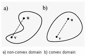
- Since the displacement of the fluid nodes is solved by applying the Laplace equation, the fluid domain is preferably convex so that the mesh quality can be optimally maintained. To attain a convex fluid domain in the model, the MESH-CUT command is available to provide cutting planes and lines in 3D and 2D domains respectively. The cutting planes or lines split the fluid domain into sub-domains of preferable shapes. The cut is hidden in the background and does not affect the mesh generation. Note, in contrast, that OMMM requires cutting the geometry and rebuilding the mesh and the model after modification.
- For many applications, a large part of the model is stationary. The MESH-FIX command is provided as a simple tool to manage the mesh for the stationary part, thereby reducing the complexity of the model and the computational cost. The MESH-FIX command can be applied anywhere inside or outside of a BOX, BALL, or EGROUP, and their possible combinations.
- Among other AMMM tools available, in particular, a user can specify more effective moving-mesh conditions directly by using the command BOUNDARY-CONDITION MESH as in the application of other fluid boundary conditions, although the mesh condition has no physical meaning.
- Finally, it is important to mention that, irrespective of the AMMM conditions applied, the physical conditions are always maintained.
Three-dimensional impeller driven flow problem
Figure 1 shows a schematic of a three-dimensional impeller driven problem. An ADINA FSI model is set up to calculate the impeller driven fluid flows and resultant fluid-structure interaction of a three-dimensional impeller driven flow.
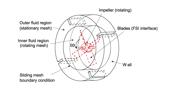
The structural part in the model is the central rotating impeller with four deformable blades that interact with the fluid. The fluid part includes the inner region, directly pushed by and interacting with the blades, and the outer region (stator), which is only indirectly influenced by the impeller.
The difficulty in this FSI model is to maintain the fluid mesh quality during the physical FSI interaction and the large arbitrary “rigid-rotation” in the inner region, while keeping the outer region fluid mesh fixed. The main conditions applied to the model are described below.
- In order to simplify the model, the two fluid regions are completely separated in mesh generation and physically connected by the application of the Sliding-Mesh Boundary Condition (SLM). This setting makes the moving-mesh control much simpler in AMMM.
- The mesh in the outer region is completely fixed by use of the MESH-FIX command. The displacement variable in this region is then removed from the solution system.
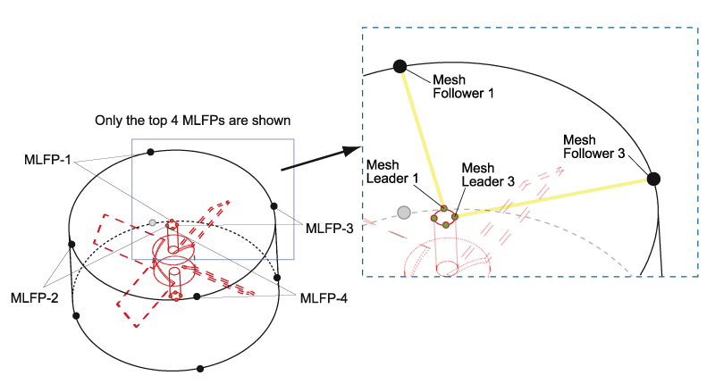
- The moving mesh in the inner region is controlled by 8 MLFPs (to take into account the symmetry), symmetrically located at the top and bottom. The leader nodes are located on rotating impeller, and the follower nodes are located at the inner part of the SLM (see Figure 2, which shows the top 4 MLFPs). The CLOSEST-DISTANCE option between the pair is selected and the follower is also set to SLIDE on the SLM. By this setting, the follower slides on the boundary while keeping the closest distance to the leader.
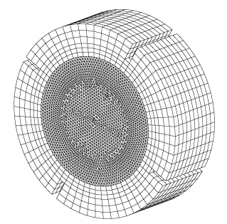
The fluid mesh is shown in Figure 3, where the inner region is meshed as a whole geometry body using a free-formed mesh because of physical complexity. The outer fluid region is relatively simple and a rule-based mesh is used. Note again that the meshing process is independent of the AMMM setting and the mesh is untouched when the solution has been completed.
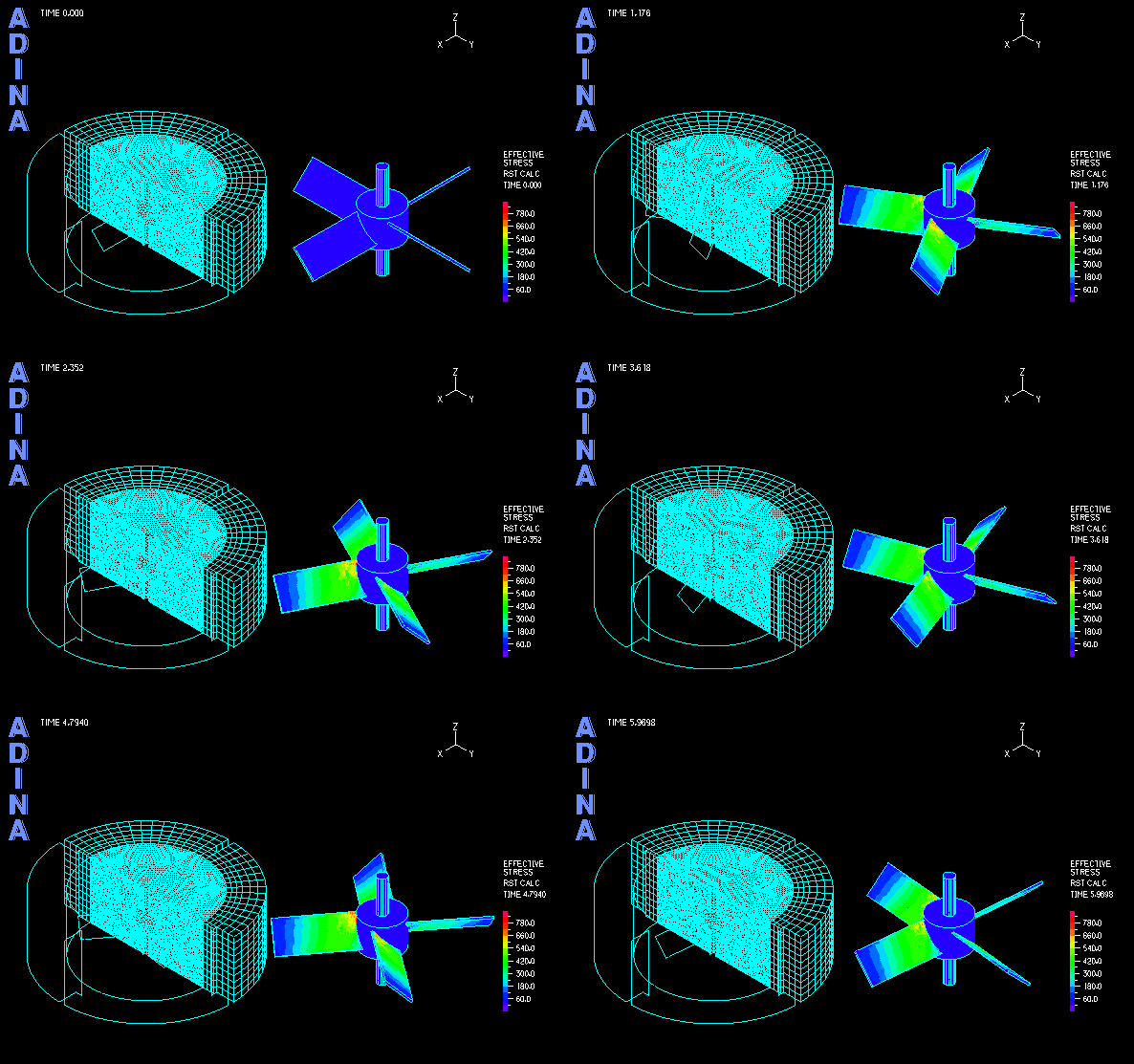
The computation of transient analysis is performed in a few cycles until both the fluid and solid solutions reach periodic steady state. The movie at the top shows the transient fluid solution. Using the AMMM, the fluid mesh quality is well maintained during the large rotation of the inner region. Figure 4 shows the fixed outer mesh and the rotated inner mesh, together with the fluid stress effect on the impeller blades.
A three-dimensional shock absorber model
Another common fluid-structure interaction application is the analysis of shock absorbers. A typical shock absorber includes a piston and a cylinder with a few side orifices as illustrated in Figure 5, hence a three-dimensional analysis is best performed.
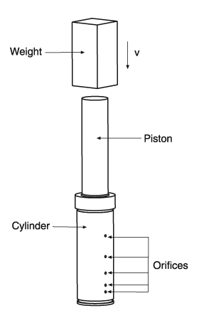
In our problem, a weight hits the piston rapidly to simulate, for example, a car accident. The piston then moves and compresses the fluid inside the chamber of the cylinder. The orifices will be shut off while the piston is moving down, thereby controlling the fluid outflow and internal pressure buildup.
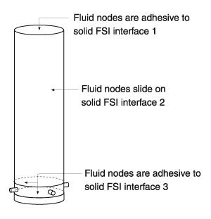
- The 3 FSI interfaces and the associated AMMM conditions are illustrated in Figures 6 and 7 respectively.
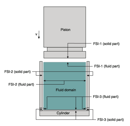
Figure 7 Fluid moving-mesh conditions in the shock absorber model
- At the top FSI interface, the AMMM condition is simply set to be ADHESIVE to the solid interface 1 (piston). Note that the ADHESIVE condition forces the fluid nodes to move simultaneously with the solid boundary.
- At the side FSI interface, the AMMM condition is simply set to be SLIDE on the solid interface 2 (cylinder). The SLIDE condition means that the fluid nodes on the interface slide “freely” on the solid boundary subject to other AMMM conditions applied.
- In order to reduce the difficulty of modeling the orifice shut-off and the resultant loss of accuracy, the orifices are relocated to be close to the cylinder bottom. Fortunately, the uniform pressure-like solution from the slightly compressible fluid model makes the relocation both possible and effective. The velocity conditions with associated arrival times are then applied to individual orifices to simulate the shut-off by the piston.
- Using the fluid modeling technique in (4), the ADHESIVE AMMM condition can be directly applied on the bottom and the cylindrical zone near the bottom of the cylinder where the orifices are located.
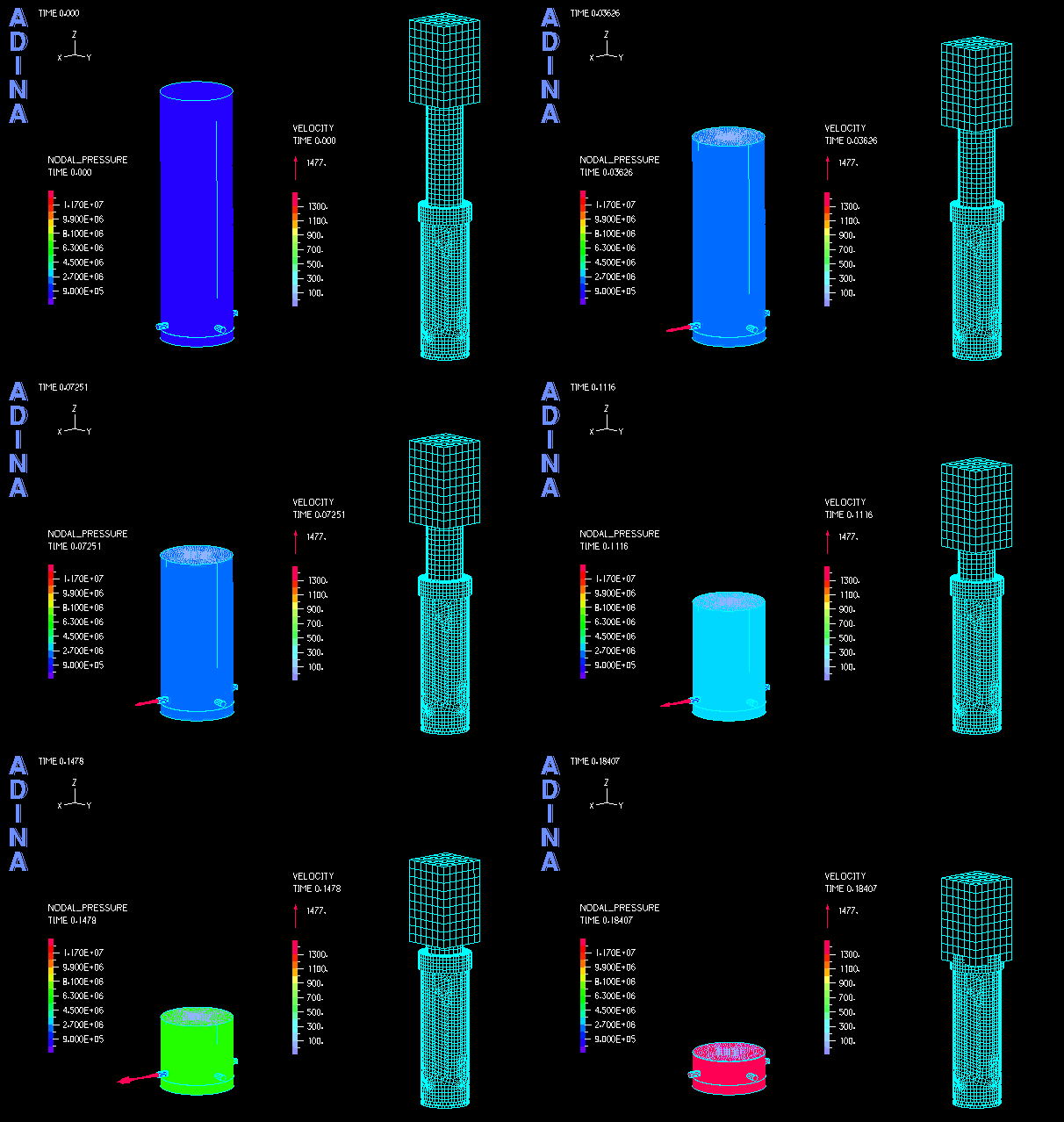
The solution of the shock absorber is shown in the movie of Figure 8. It is clearly seen that the fluid pressure quickly builds up as the piston moves down, and that the individual orifices are shut off during this process.
Figure 8 The solution of the shock absorber model
Conclusion
ADINA’s new Advanced Moving Mesh Method (AMMM) provides a powerful tool for the analysis of complex fluid-structure interactions and moving mesh applications. With AMMM, many difficult ALE-related problems are now solvable in a relatively easy and transparent manner. The AMMM also provides great flexibility by accepting models prepared in other pre-processors.
Keywords:
FSI, moving mesh, AMMM, Advanced Moving Mesh Method, geometry-independent moving mesh control, ALE.
