This blog is a part of the series Tunnel your way to success with PLAXIS.
PLAXIS offers a wide range of tools to the Tunnel Engineer, which can be combined to generate almost any ground, tunnel, and reinforcement system geometry.
Node-to-node anchors
As their name indicates, node-to-node anchors provide an elastic connection between two non-adjacent nodes. These line elements only interact with the finite element mesh at their end nodes, which makes them especially indicated for modelling the free (unbonded) length of ground reinforcements.
Embedded beams
Contrary to the node-to-node anchors, embedded beams are… well, embedded. They are elastically connected to the ground along their whole length, and at the bottom. Thus, they can model almost any reinforcement element: piles and micropiles, dowels, rockbolts, forepoles, etc. They can also be connected to the end of a node-to-node anchor to model the grouted (bonded) partition of any discontinuously coupled reinforcement. Embedded beams cannot be prestressed, but node-to-node anchors can, so their combination can be prestressed through the node-to-node and transmit those stresses to the ground through the embedded beam.
Cables
If you could mix a node-to-node anchor and an embedded beam, you would get a cable. Cables are line elements that can only take axial loading. In exchange, they can be prestressed and consequently grouted, which enables them to transmit the stresses to the ground through their entire length.
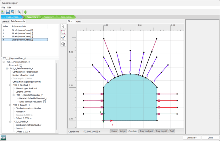
Figure 1. Combine systematic reinforcement patterns
Plates
Plates are shell structural elements. They can model any support element where one of the dimensions is significantly smaller than the other two, including both precast and cast-in-place linings or sprayed shotcrete. Plates with ribs or frames can be modelled with the addition of beam elements.
Volumes
In PLAXIS, volume elements are most commonly used for soil or rock, but they can also model solid structures, e.g. using the Concrete material model.
Interfaces
Interfaces introduce a virtual layer between a structure and the ground, enabling relative displacements between one and the other. They are invaluable for the consideration of ground-structure interaction effects.
Discontinuities
Discontinuities are similar to interfaces in that they allow relative displacements between the elements at each of their sides, but they are used within the ground, to account for the behaviour of rock fractures, faults, or any other weakness planes.
Tunnel Designer
The PLAXIS Tunnel Designer provides a one-window solution for all your tunnel analysis tools.
Although not restricted to modelling tunnels, the Tunnel Designer works by extruding a constant cross-section along a continuous trajectory. In 3D this trajectory can be horizontal, inclined, vertical, or an arbitrary planar curve, and it can be split in multiple slices. In 2D the trajectory is fixed by the plane strain assumption as a long, straight line, perpendicular to the design plane. In that context, the Convergence-Confinement Method offers a simplified way to consider the influence of the out-of-plane direction.
Cross-sections can be specified as a combination of lines and arcs or imported from files. Half-symmetrical sections can be easily defined to reduce computational cost. The cross-section can include subsections to help define the geometry of each excavation step.
Systematic reinforcement patterns can be defined parametrically on any of the segments (2D) or surfaces (3D) delimiting the opening. These can be modelled either as rods or rockbolts, using the embedded beam element, or axial-only cable bolts, using cable elements. Two-part reinforcements can also be defined, which enable splitting the reinforcement elements to account for bounded and free lengths. Free length segments can be modelled as node-to-node anchors if left ungrouted or as cable elements, which allow the formation of bonding after prestress has been applied.
In 3D, you can also use embedded beams to model the umbrella arches created by forepoling. In 2D, the influence of umbrella arches can still be captured in a simplified approach by defining an area of material with enhanced parameters.
Support and retention systems, including shotcrete, can be modelled as either thin (plates) or thick lining (volumes). Composite support systems are possible by combining multiple layers of both thin and thick lining. In 3D, transverse steel sets, frames, or ribs can be specified as girders at regular intervals. Ground-structure interaction effects can be captured by introducing interface elements between the primary lining and the ground.
Excavation sequences can be specified both within the cross-section and along the trajectory, through the use of slices. The definition of sequencing considers two default advancement methods: TBM (Tunnel Boring Machine), where the entire cross-section is excavated in a single slice, and NATM (New Austrian Tunnelling Method), where the excavation sequence may span multiple slices. Even more complex excavation sequences can be defined by splitting tunnels longitudinally, which allows for independent advancement rates between the split tunnels.
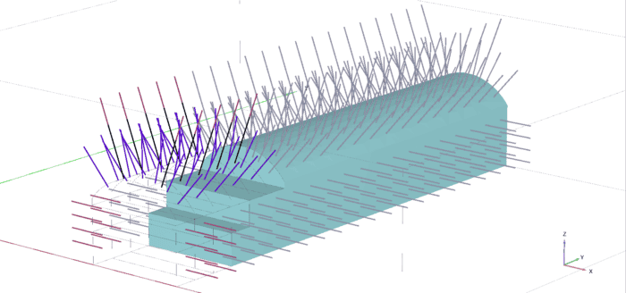
Figure 2. Sequence of construction
So how do you deal with changing cross-sections?
Multiple tunnels! Section changes can be automatically resolved using the blend surfaces tool. Multiple tunnels can also be used to resolve more complex geometries. Tunnels can intersect each other, and other volumes, which enables defining junctions, adits, cross-passages, and complex excavation sequences; vertical or inclined tunnels can be used to model shafts and stairwells. Naturally, tunnels can also intersect the topography, to form portals.
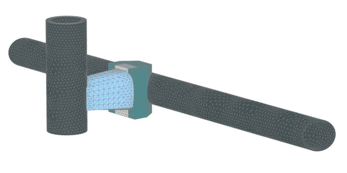
Figure 3. Model tunnels, caverns, shafts, and any other underground construction
Conclusion
Modelling tunnels for analysis is as easy as it ever was. While you can generate almost any underground geometry using basic PLAXIS building blocks, the Tunnel Designer provides a centralised toolbox that will greatly accelerate your modelling of underground constructions in both 2D and 3D.
As we continue to improve the Tunnel Designer in PLAXIS 2D and 3D with a comprehensive range of functionality, we also strive to provide a pleasant modelling experience. Do you have any suggestions or comments on how we are doing? Let us know!