This blog is a part of the series Tunnel your way to success with PLAXIS.
Introduction
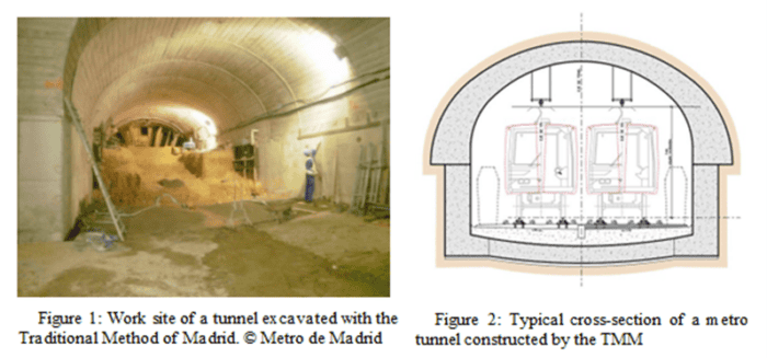
The Traditional Method of Madrid is a method for tunnel construction that has been used for tunnelling in the Madrid Metro network since 1917 (Melis Maynar, M. 2012). The method uses a distinctive excavation sequence that comprises the division of the crown in a series of small excavations that are successively supported by a combination of timber struts, steel waler beams and timber planks during the excavation stage and directly followed by the permanent lining installation. The permanent lining is unreinforced casted concrete (typically C30/37); thus, no reinforcement is normally used. The construction of the walls and invert of the tunnel follow several metres behind, also in the same fashion as an unreinforced concrete permanent liner.
The multiple phases and diverse struct distribution of stresses around the tunnel excavation.
This article presents the methodology followed for the calibration of bidimensional models of tunnels undertaken by the TMM, via three-dimensional models. Furthermore, it discusses the assumptions and calculation strategies used to achieve an appropriate adjustment that permits the validation of 2D models, which can be used for early stages of a similar project.
The Traditional Method of Madrid
There are many examples of the application of this method in an urban environment. Experience with tunnels built using this method in the soils of Madrid has demonstrated the safety of the works. The sequence of works follows a number of steps refined and improved over the years by the experience of Madrid’s miners and tunnel engineers, and by studding thural elements have represented traditionally a challenge from the point of view of the stress-strain calculation of sections for design, since the remarkable three-dimensional effect of the excavation behaviour requires the development of three-dimensional SSI models, which may not be available for the project.
In this scenario, it is usual to perform bidimensional approximations of the problem that allow the analysis time to be reduced. However, this approach requires a careful analysis of the hypothesis considered to obtain results that are sufficiently adjusted to reality in terms of ground movements and re lessons learned of past projects.
Although this construction process requires specialised labour, it is a very versatile method, which allows a high degree of adaptation to the constraints of an urban environment.
This methodology is based on the principle of carrying out small excavations (less than 5 m2) as shown in Figure 1, which greatly limit the open excavation face, to guarantee its stability during construction. The excavation begins with an advance gallery that is gradually shored and widened to form the crown of the tunnel, always with a temporary support for each widening stage. In this way, the open face for each excavation plane is reduced and, therefore, the stability conditions are more favourable.
This advance gallery also acts as a pilot tunnel to identify any contingency or uncertainty about the state of the soil, thus allowing the adaptation of the construction procedure to respond to these singularities. The contingencies can include “toolbox” items such as reducing the round length or install timber planks at the open face.
Depending on the dimensions of the tunnel section and the operating features of the construction equipment, the excavation can be divided into three general phases, called the top heading, bench and invert, in such a way that the bench is carried out after the top heading, with a certain amount of distance in between, and always acting on a single side of the tunnel walls, so as not to remove the support of the crown previously executed.
Normally, advance lengths of between 1.25 and 2.5 m are used, depending on the terrain crossed, with shoring systematically installed, although there are exceptions linked to singular sections, either due to geotechnical conditions or to the need to adapt the construction methodology in sections with special needs, such as at junctions or areas where 2 galleries intersect.
Immediately after crown’s excavation, the formworks are installed and unreinforced concrete is casted, thus controlling the deformation of the ground, giving the concrete final liner the task of containing and limiting the deformation of the ground.
The casting of the crown is carried out by pumping “in situ”. Subsequently, the excavation of the bench is carried out, followed by the casting of the unreinforced concrete of the side walls. The section is finally completed by casting the invert bottom slab.
Finally, a schematic of a typical construction sequence of a tunnel excavated using the Traditional Method of Madrid is shown in Figure 2 above.
Traditional Method of Madrid construction sequence
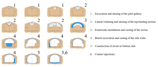
The typical construction sequence of the method is described in Figure 3 and explained below.
Figure 1: Construction sequence of the Traditional Method of Madrid
1 to 3 – Top heading: Instability phenomena, such as collapse of the tunnel face or collapse of the crown, are a conditioning factor in large tunnels excavated in soft ground, so that the effectiveness of the method requires exhaustive control of the progress of the excavations and the integrity of the lining executed. The use of temporary works as shoring, in which the excavated ground is supported by timber planks, which are supported on longitudinal steel waler beams and these are finally supported by sub-vertical timber struts. The division of the top heading into several excavation phases contributes to a better control of the stability of the tunnel. On the other hand, the excavation of a pilot tunnel of reduced dimensions provides value characterisation of the ground ahead, detecting the areas of poor geotechnical quality and any potential issue with stability. For the same reasons, this characterisation will enable the shoring system to be adapted accordingly. To cast the top heading, the steel walers are left in place and the subvertical timber struts, in the projection of the formwork, are removed. Several sets of formworks are used to allow the concrete of the top heading to cure for at least 2 days.
4 – Bench: Once the crown has been casted, the excavation of the central bench is carried out with an offset of 5 or 6 rings from the face. When the dimensions of the tunnel allow it, it is excavated leaving a 1.0 to 1.5 m safeguard platform, so that the thrust that the crown transmits to the ground underneath does not form failure planes that could give rise to settlements and failure of the crown. As indicated above, the excavation of the bench stage, and therefore the casting of the side walls, will be carried out in two counterforts or walls, excavating, and casting alternately to always guarantee the support of the crown and adopting the necessary measures to avoid its deconfinement due to settlement in its support areas. To achieve this objective, it will be essential to excavate each wall in modules of the same length as the advance of the crown, making the joint of the top heading rings coincide with the centre of the future side wall, so as not to completely remove one ring of the crown. For the reasons given above, never excavate two facing each other at the same time.
5 and 6 – Invert and Contact injections: Finally, the invert is executed, where the corresponding excavation is carried out in a length generally of 2 to 4 rings, and then the concrete is placed to completely close the section. After the construction of the invert, the back of the crown is grouted using post-drilled holes. The aim of this process is to fill any gaps that may remain at the crown extrados between the concrete, the timber shoring, and the excavation profile, and to waterproof the contact joints between the rings. The injection pressure must be limited to avoid excessive loads on the lining, usually limited to 1 bar.
SOIL-STRUCTURE INTERACTION Models
Firstly, it is necessary to create two models: a three-dimensional and a two-dimensional SSI model, based on the first one. To generate both models, the finite element calculation programme PLAXIS 3D and 2D were used, respectively.
A cross-section of a metro tunnel with a lithology typical of the northern area of Madrid was chosen. The geological stratigraphy of the case used for the present analysis is formed by a superficial layer of Quaternary made ground, followed by a set of Tertiary materials, namely a layer of “Arenas Tosquizas” (clayey sands), “Toscos” (sandy clays) and finally a layer of “Peñuelas” (mainly over consolidated clays) (Rodríguez, J.M. 2000). The total covering of the tunnel is equal to 12.9 m, of which 12 m are Tertiary materials and only 0.9 m represent the superficial “Relleno Antrópico” (made ground). The stratigraphy of the models as well as their layers thicknesses are summarised in the Table 1. A typical section of a metro tunnel has been used for both models, as shown in Figure 2 previously. Furthermore, Figure 4 shows the two models in which important features of these 2 models can be observed, among others, the geometry of the model, the mesh, and the stratigraphy.
Table 1: Summary of the stratigraphy of the models
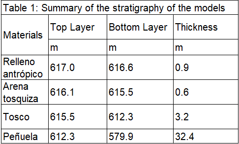
Figure 2: 2D SSI Model (Right)
Regarding the properties of the models, it should be noted that the soil was assumed to be dry, based on the results of the geotechnical campaign. Therefore, a drained type of calculation has been carried out. On the other hand, the Hardening Soil constitutive model was used to express the stress/strain behaviour of the ground and their properties are summarised in Table 1.
Table 2: Hardening soil ground parameters
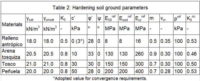
*Adopted value for convergence requirements.
2D SSI Model
The two-dimensional model is intended to be a reproduction of the three-dimensional model, presented in the previous section. The dimensions of this model are 80 m wide and 37 m deep. The location of the tunnel as well as the stratigraphy is the same in both cases.
In the same way as for the three-dimensional case, the final lining of the tunnel has been designed as volumetric elements with dummy plates at its centroids Furthermore, the timber shoring and the timber struts have been considered to simulate the temporary support of the tunnel advance, the former have been modelled with plates and the latter with embedded beam rows.
Regarding the two-dimensional model, it should be noted that the Mstage numerical calculation tool is used to reproduce the effect of confinement during excavation that occurs in 3D models. This parameter is key to calibrate the model, as described below.
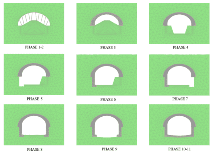
The calculation phases used to simulate the construction of a tunnel using the TMM in two dimensions are listed below, with the relevant relaxation obtained from the calibration.
- Phase 0: Initialisation of in-situ stresses; using K0 method.
- Phase 1: Excavation of top heading and temporary lining; soil relaxation up to 79%.
- Phase 2: Virtual phase for simulation 3D behaviour of distance to excavation face; soil relaxation equal to 40%.
- Phase 3: Concrete casting of top heading.
- Phase 4: Excavation of central bench.
- Phase 5: Excavation of right bench; soil relaxation equal to 48%.
- Phase 6: Concrete casting of right lateral wall.
- Phase 7: Excavation of left bench; soil relaxation also equal to 48%.
- Phase 8: Concrete casting of left lateral wall.
- Phase 9: Excavation of the invert.
- Phase 10: Concrete casting of the invert.
- Phase 11: Section completed with concrete of 7 days old.