This blog is a part of the series: Your Guide for Soil Improvement with PLAXIS
Prefabricated vertical drains (PVDs) are essential tools in geotechnical engineering, particularly for improving the properties of soft soils. By facilitating drainage and accelerating consolidation, PVDs play a critical role in the stability and settlement of soil. The use of PLAXIS for modelling drains allows engineers to predict and analyse their behaviour effectively. This article will guide you through the process of modelling PVDs in PLAXIS, covering key aspects such as geometry setup, material properties, boundary conditions, and result interpretation.
What Are Prefabricated Vertical Drains?
PVDs are geosynthetic materials installed vertically into soft soils to accelerate the consolidation process by providing efficient drainage paths for excess pore water pressure. This technology is commonly used in large-scale infrastructure projects, where rapid settlement and soil stabilization are critical.
Why Model PVDs in PLAXIS?
Numerical modelling of PVDs using PLAXIS offers several benefits. It helps engineers understand the behaviour of PVD-improved subsoil, predicts settlement, monitors pore pressure dissipation, and ensures overall stability. Moreover, the efficiency of PVDs can be significantly enhanced by applying techniques like vacuum consolidation, which can also be modelled in PLAXIS.
Key Steps in PVD Modelling
- Geometry setup
The first step in modelling PVDs in PLAXIS is to set up the geometry of the project. This involves defining the layout of the PVDs while considering factors such as drain spacing, depth, and arrangement. The most common arrangement is a grid layout, which ensures uniform consolidation across the area. PLAXIS models are typically defined in 2D plane strain, though 3D slice models can also be employed when necessary.
- Material properties
Assigning accurate material properties is crucial for successful modelling. Engineers need to ensure that the properties of the PVDs are compatible with the surrounding soil.
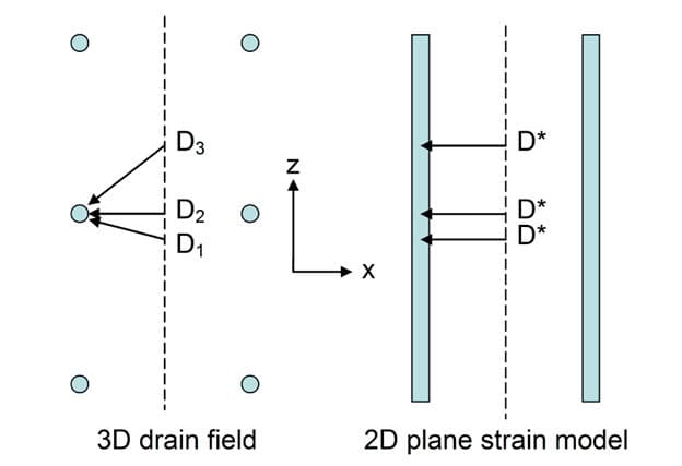
This process first includes defining the permeability of the materials, which is critical for simulating the drainage and consolidation process. For 2D plane strain models, the use of a calibrated equivalent horizontal permeability to simulate radial consolidation effects more accurately is necessary (see Figure 1). Techniques developed by experts like Hird (1992), Indraratna (2005), and Chai (2001) are in this context particularly useful. But while formulas provide initial equivalent permeability estimates, further calibration through trial and error is often necessary to achieve accurate results.
For very soft soils, constitutive models, such as Soft Soil or Modified Cam-Clay, are recommended to accurately capture the mechanical behaviour. If secondary consolidation is to be considered, the Soft Soil Creep model is recommended.
Figure 1: Modelling of drains in a 2D plane strain configuration
- Boundary conditions and analysis setup
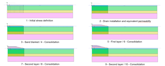
Correctly applying boundary conditions and setting up the analysis is vital for accurate results. This process involves specifying initial conditions, such as initial stresses, and defining drainage boundaries for the correct assessment of excess pore water pressure development. The construction stages typically follow a sequence, starting with initial stress definition, followed by drain installation, then subsequent consolidation phases. Each stage must be carefully modelled to reflect the correct stress history of the soil as illustrated in Figure 2.
- Results interpretation
After running the simulation, interpreting the results is key to assessing the effectiveness of the PVDs. Important indicators include surface settlement, lateral deformation, and excess pore pressure. These results help engineers evaluate whether the PVDs are functioning as intended and making necessary adjustments to improve their performance.
Additionally, phi-c reduction analysis can be used to evaluate safety during embankment construction. This method helps quantify the stability of the soil and the effect of PVDs over time by progressively reducing the soil’s shear strength parameters (friction angle, φ, and cohesion, c) until failure is observed. By running this analysis at different stages of consolidation, engineers can observe how the PVDs enhance stability and reduce the risk of failure as the embankment is constructed and consolidated over time.
Figure 2: Typical construction stage sequence for embankment construction on PVD
Advanced Considerations
Smear zones
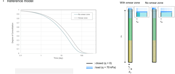
During the installation of PVDs, a disturbed area known as the smear zone forms around the drain. This zone has lower permeability than the surrounding undisturbed soil, which can reduce the effectiveness of the PVDs. Therefore, modelling the smear zone in 2D is important, because ignoring it can lead to overestimating the PVD’s effectiveness. Accurately incorporating it ensures that the model reflects real-world conditions, especially in very soft soils where the smear effect is more pronounced. Accurate modelling of the smear zone could be essential, as it might significantly impact the overall consolidation process as shown in Figure 3.
Figure 3: Effect of smear consideration on degree of consolidation evolution
Vacuum consolidation
Vacuum consolidation is a technique used to enhance the performance of PVDs by applying suction to accelerate consolidation (see Figure 4). In PLAXIS, this is modelled by applying negative water pressure along the drains (by defining groundwater glow boundary conditions along internal model lines), which generates a large water pressure gradient toward the PVDs without desaturating the soil. However, maintaining consistent suction pressure can be challenging, and this needs to be carefully modelled to reflect real-world conditions.

Figure 4: Effect of vacuum suction pressure on embankment settlement evolution
Conclusion
Modelling PVDs in PLAXIS is a complex but essential task in geotechnical engineering. By following the steps outlined in this guide, engineers can optimize the performance of PVDs, ensuring faster and more uniform soil consolidation. Whether you are working on large infrastructure projects or smaller developments, understanding how to effectively model PVDs in PLAXIS will contribute to safer and more efficient construction practices.
References
Chai, J.C., Shen, S.L., Miura, N. and Bergado, D.T. (2001)., Simple method of modelling PVD improved subsoil. Journal of Geotechnical Engineering, ASCE, 127(11), 965-972.
Hird, C.C., Pyrah, I.C., and Russell, D. (1992). Finite element modelling of vertical drains beneath embankments on soft ground. Géotechnique, 42(3): 499–511.
Indraratna, B., Sathananthan, I., Bamunawita, C. and Balasubramaniam, A.S. (2005)., Theoretical and numerical perspectives and field observations for the design and performance evaluation of embankments constructed on soft marine clay, Ground Improvement, Elsevier, 199-230.
![Graph showing two curves labeled "Vacuum" (red) and "No Vacuum" (blue) across time. The vertical axis is labeled "y [mm]" and the horizontal axis is labeled "Time [sec].](https://blog.bentley.com/wp-content/uploads/emea-bog-2.5-1.png)
