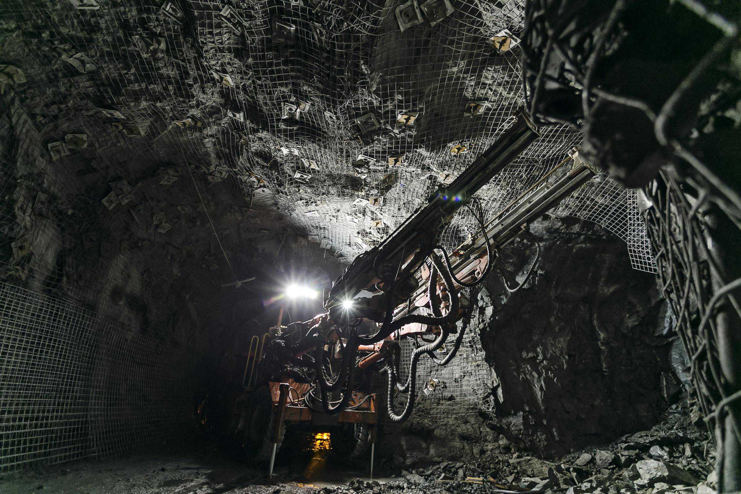
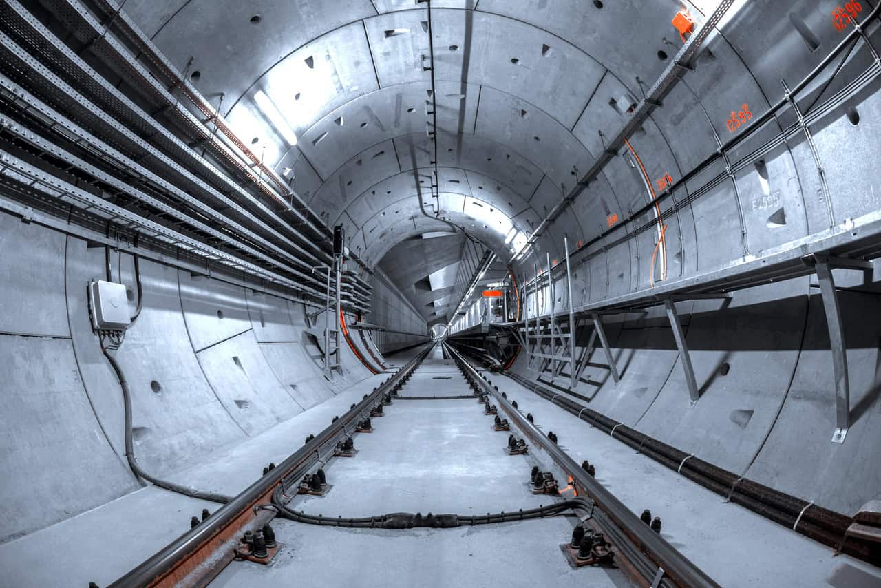
Rock masses are characterized by the existence of distributed joints. The mechanical properties of jointed rock masses are strongly dependent on the properties and geometry of the joints. Jointed rock masses are usually weaker, and more deformable and are highly anisotropic when compared with intact rocks. Constitutive modeling of jointed rock masses has long been a subject of interest and numerous models have been developed in attempts to simulate their mechanical responses. There are two groups of these models: discrete models and continuum models as summarized by Cai and Horii (1993):
- In the discrete models, the joints are implicitly modeled. This often leads to quite large and often complex problems in the case of pervasive and closely spaced joints. Because of the limitations of geological survey methods for joints in situ, joints in a rock mass are usually treated as an assemblage and joint positions which are understood statistically. Therefore, it is impractical to model every joint in a deterministic way.
- In the continuum models, the jointed rock mass is treated as a continuum with equivalent material properties which reflect the effect of the joints. This approach circumvents some of the difficulties in the discrete method and is used in PLAXIS in rock mechanics. The PLAXIS jointed rock models fall into that second category.
Jointed Rock Model (Standard)
The Jointed Rock model was conceived and implemented as an anisotropic elastic-plastic material model which assumes that the behavior of the intact rock is linear elastic while that of the joints is elasto-plastic.
- The rock matrix remains elastic but with the possibility to offer different stiffness values in the directions respectively normal and perpendicular to the major stratification direction (first plane) as shown in Figure 1.
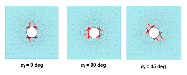
- Plasticity could solely occur in (up to) three stratification or fault directions (planes) using independent cohesion, friction angle, dilation angle, and tensile strength on each plane. Such directional perfectly-plastic behavior is illustrated in Figure 2 on a tunnel excavation in rock mass.
The application of the Jointed Rock model is justified for material that shows parallel joint sets or joint families, the spacing between which has to be small compared to the overall dimensions of the structure.
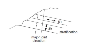
Figure 2: Influence of the plane angle on the plastic point pattern.
Isotropic Jointed Rock Model (UDSM)
A companion constitutive model has also been developed as a user-defined soil model, namely the Jointed Rock model with overall Mohr-Coulomb failure criterion (Iso-JRMC). It is a combination of the native Jointed Rock model but with an isotropic elastic part (instead of orthotropic) and the Mohr-Coulomb model. Plasticity will still primarily occur in (up to) three stratification or fault directions (planes) using cohesion, friction angle, dilation angle, and tensile strength on each plane, while an overall MC criterion (based on principal stresses) will also be considered in all directions for the rock matrix. Because of this, it is possible that failure occurs along the sliding planes as well as in the intact rock, which is not possible for the standard Jointed Rock model.
The advantage of this model over the standard Jointed Rock model in PLAXIS is that the latter may lead to ”locking” if a potential failure mechanism requires other than the predefined failure directions to develop. The Iso-JRMC model will overcome the ”locking” issue since it may (eventually) fail in other directions as well (according to the overall Mohr-Coulomb criterion along the maximum shear direction that may be different than any of the pre-defined directions), such that a continuous failure mechanism may be obtained. This has been perfectly illustrated by Stelzer (2015) on the stability assessment of a rock slope.
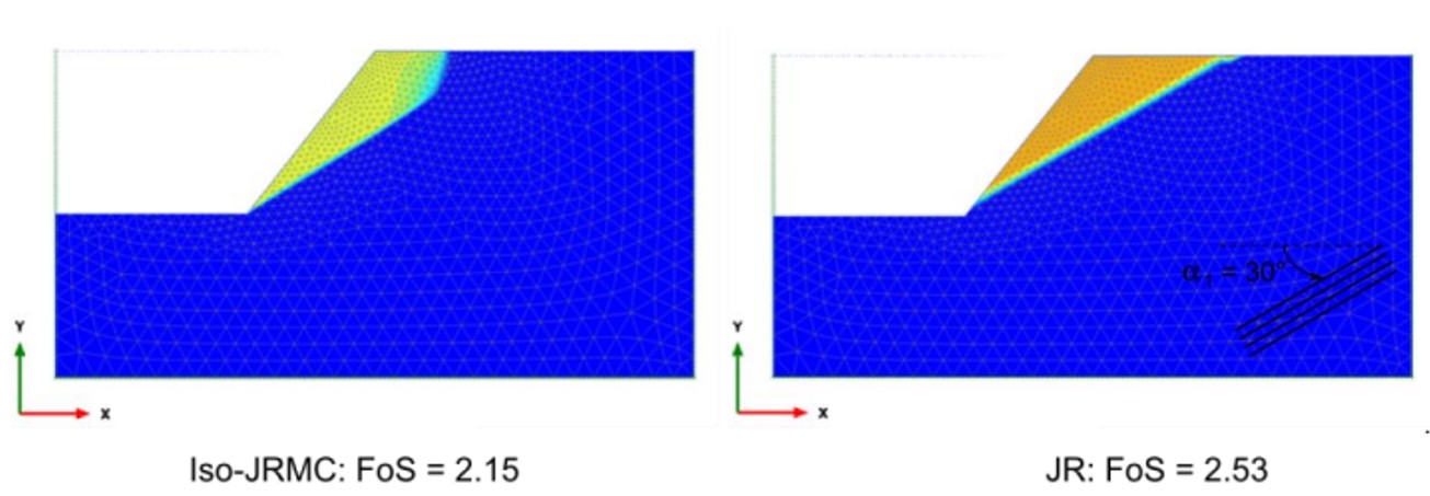
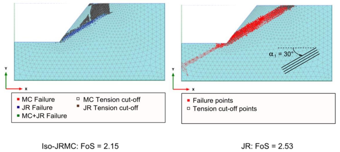
Figure 3: Comparative simulation between JR and Iso-JRMC models (Seltzer. 2015).
References
M. Cai and H. Horii (1993) – A constitutive model and FEM analysis of jointed rock masses, International Journal of Rock Mechanics and Mining Sciences & Geomechanics, Vol.30, Issue 4, pp. 351-359.
M. Stelzer (2015) – Numerical Studies on the PLAXIS Jointed Rock Model, Master Thesis, TU Graz.
Read our blog How to Model Rock Engineering Problems in PLAXIS Geotechnical Analysis Software
