The problem of changing water conditions is omnipresent in geotechnical engineering. Groundwater is systematically found beneath the Earth’s surface in soil pore spaces and rock formation fractures. The flow of groundwater is a fundamental aspect that controls the strength and compressibility of soil, impacting soil’s ability to sustain structural loads. The study of groundwater is essential for geotechnical engineers who construct building foundations, tunnels, water conveyance channels, dams, mines, and other structures.
In this context, PLAXIS 2D and PLAXIS 3D are fully equipped with a complete set of tools to model changes of pore water pressure and, more specifically, dewatering, along with its influence on soil mechanical behavior.
Terzaghi principle of effective stress
The Terzaghi principle is a fundamental concept used in geo-mechanics in general, and in PLAXIS in particular, to understand how a change of water pressure induces change of soil stresses and associated soil deformations. The Terzaghi principle states (in a very symbolic way) the following:
Total stress σ = Effective stress σ’+ Pore water pressure u
Figure 1: Terzaghi effective stress principle
The total stress σ is balanced by the applied load (soil weight, infrastructure weight, service loads), whereas all strength and stress-strain characteristics of the soil are linked to changes in effective stress σ’.
Lowering the groundwater will reduce the pore water pressure u and hence will cause an increase and redistribution of soil effective stresses, which will then lead to the settlement and evolution of active and passive pressure in surrounding buried structures.
Water levels and hydrostatic pore pressure distribution
By default, PLAXIS computes pore water pressure fields in the model based on a hydrostatic distribution (phreatic method). In such situations, water is implicitly assumed to be at rest such that pore pressure depends on depth only: u = γw.depth.
Figure 2: Steady-state pore pressure definition on a 3D model
The definition of water levels in PLAXIS can be performed during soil stratigraphy definition when defining boreholes or within Flow mode. The Flow mode enables the definition of additional water levels different than the initial one. Additional water levels might then be referenced (globally, or locally in some limited numbers of soil clusters in the model) to simulate the process of dewatering.
(a) PLAXIS Input definition
(b) Considered pore water pressure distribution in PLAXIS Output
Figure 3: Dewatering by means of the phreatic method
Groundwater flow analysis
The FE method can also be used in PLAXIS for groundwater flow modeling to analyze hydrogeological problems, such as dewatering, in multilayer soil profiles. Such types of analysis can be run in either a steady-state model or in a time-dependent model. Sources and wells can be placed in various aquifers inside the PLAXIS model. Also, PLAXIS enables the calculation of the groundwater flow around and the leakage through watertight structures, such as sheet pile walls or cut-off walls.
Such groundwater analyses require the definition of additional parameters for the constitutive materials, such as:
- Permeability values
- Porosity
- Unsaturated zone behavior eventually
Along with specific flow boundary conditions, including:
- Prescribed head of water flow
- Closed flow
- Seepage flow boundary
- Drains
- Wells (both infiltration and extraction)
- Precipitations
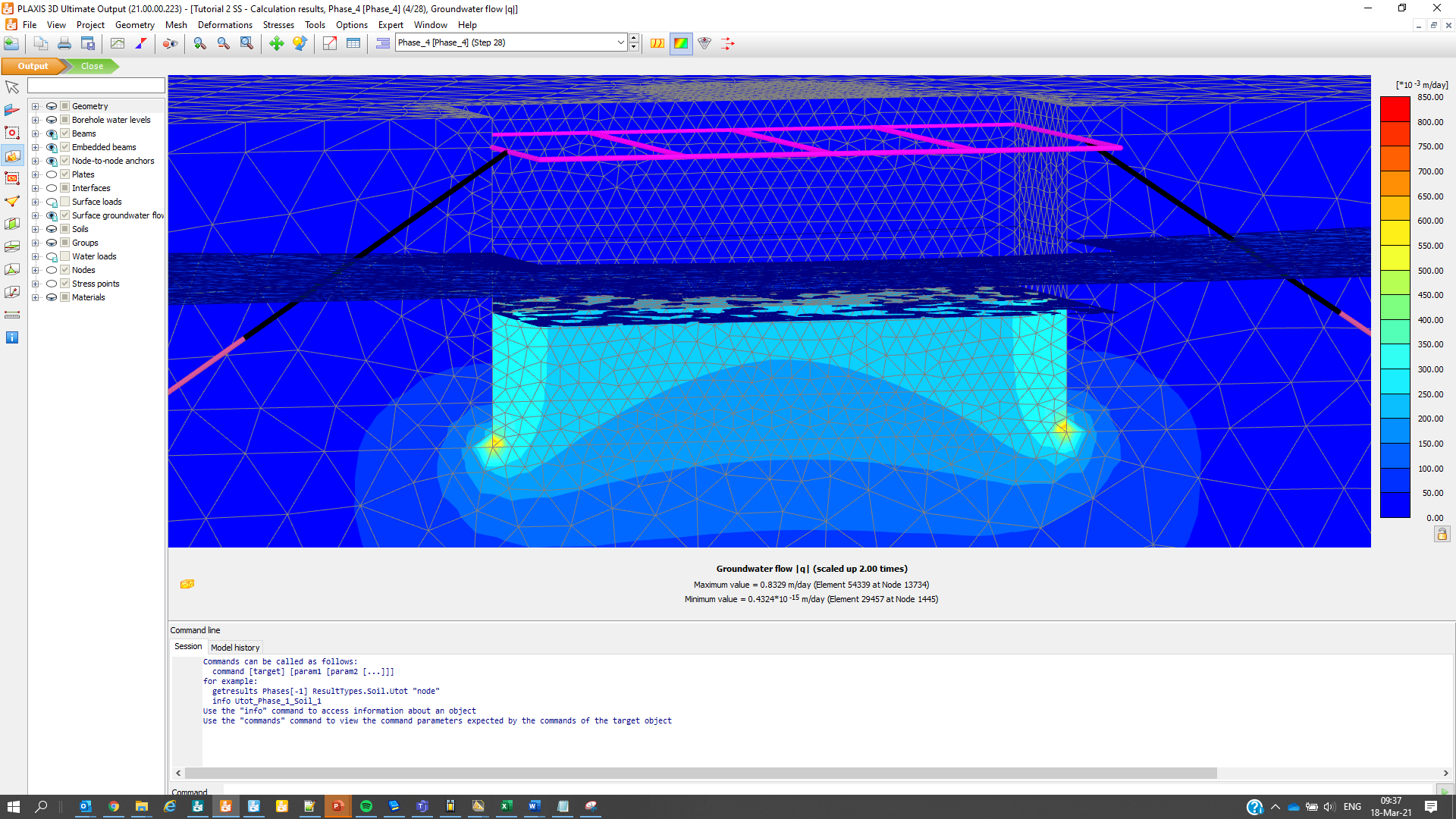
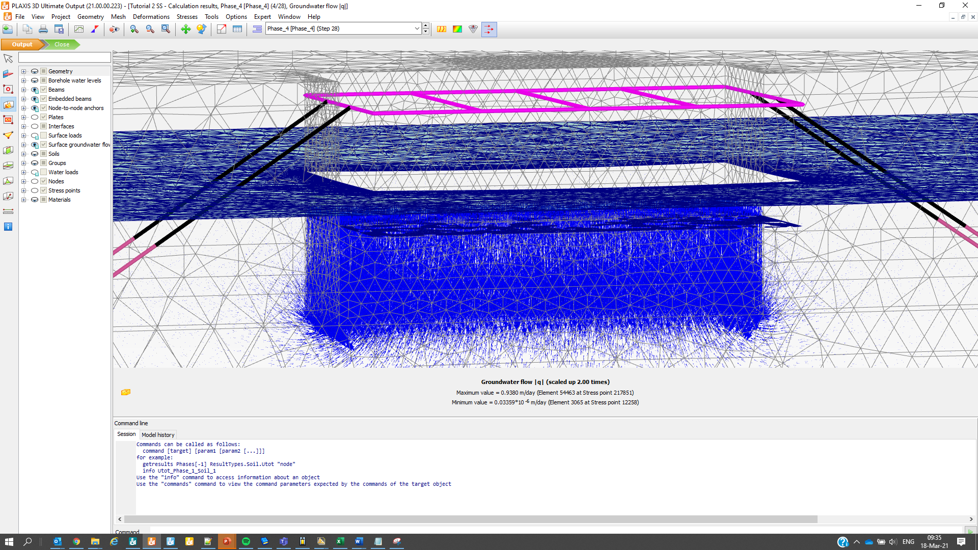
For the particular case of watering, steady-state groundwater flow analyses are usually carried out for relatively permeable situations for the sake of finding the updated pre-water pressure field, along with the resulting water level and the water flow distribution at a steady state regime, as shown in Figure 4.
(a) Contour plot of groundwater flow
(b) Vector plot of groundwater flow
Figure 4: Dewatering by means of the groundwater flow calculation method
Discover the PLAXIS Productivity Strategies series featuring blogs, LinkedIn Live sessions, and webinars.
Learn more about PLAXIS with Bentley’s eStore:
Check out the Concept to Construction series including the PLAXIS session here.
Interested in PLAXIS soil models? Find more resources.
Want to learn the specialized material models in PLAXIS 2D and 3D?
Get access to new educational PLAXIS videos to explore the benefits and value of using PLAXIS.
For the price and the amount of Keys included in PLAXIS Virtuoso Subscription, please visit this page.
Want to learn more about what PLAXIS can do for you? Don’t hesitate to contact our geotechnical experts. We are happy to help.


