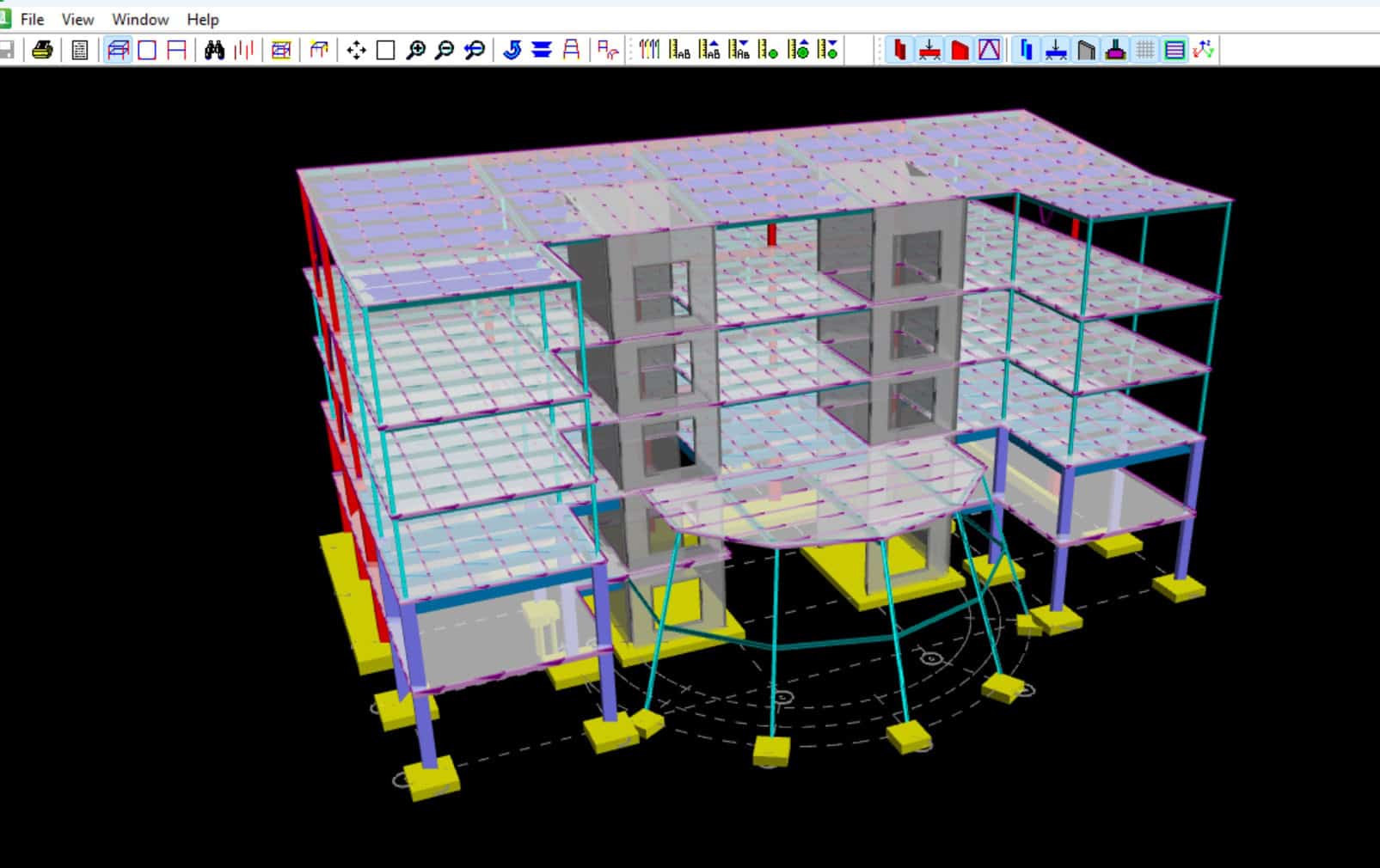
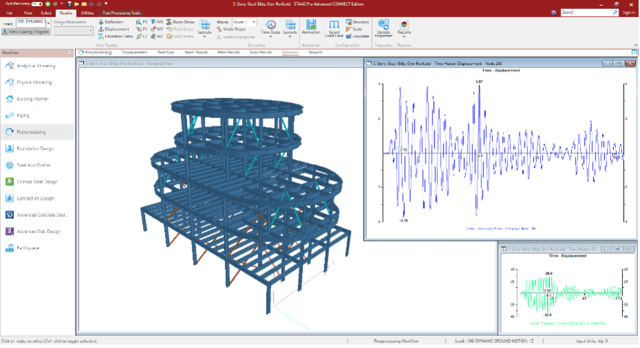
STAAD.Pro structural analysis and design software from Bentley has been widely used for designing steel and concrete structures by engineers across the globe for decades. In recent versions of the software, significant enhancements have been made to the concrete design capabilities through the introduction of the Advanced Concrete Design workflow. The new workflow not only enables the analyzed model to be designed as per concrete codes like ACI 318-14, but also allows the generation of design reports and goes far beyond in terms of creating detailed drawings, bills of quantities, and bar bending schedules. This blog post outlines these enhanced concrete design capabilities and how engineers can leverage these in their own concrete design projects.
This article focuses on the following topics:
- Analysis considerations for concrete structures
- Beam, column, and wall design, and seismic detailing
- Generation of reports and drawings
Analysis Considerations for Concrete Structures
In lieu of a more detailed nonlinear analysis, the code permits linear analysis of concrete structures with appropriate stiffness reductions as outlined in section 6.6.3.1.19(a) of the AIC 318-14 code to account for cracking and creep. One can account for such stiffness reductions in STAAD.Pro through the use of Property Reduction Factors. An elastic second order analysis as mentioned in section 6.7 of ACI 318-14 is required to account for slenderness effects.
In STAAD.Pro, the iterative P-Delta analysis, which includes both large and small delta effects, can be used for this purpose. The analysis approximations involved in magnifying column moments from a first order analysis using Moment Magnification Factors, are thus completely eliminated by carrying out a more accurate second order analysis like a P-Delta Analysis. One needs to combine loads using REPEAT LOADS in lieu of LOAD COMBINATIONS for this type of analysis to properly account for the P-Delta effects.
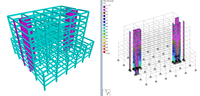
Different types of lateral force-resisting systems like moment frames, braced frames, shear walls, and dual systems can be adequately modeled in the software. Shear walls can be modeled using a mesh of plates. The stiffening effect due to concrete floors and decks, which behave as rigid diaphragms, can be included in the analysis by using the Floor Diaphragm feature. This allows one to account for the effect of the slab without actually modeling it using a mesh of plates, which in turn helps in reducing the problem size and complexity. The Floor Diaphragm feature also helps in accounting for torsion effects resulting from eccentricity between center of mass and center of rigidity and also accidental torsion.
Beam, Column, and Wall Design, and Seismic Detailing
Beam Design
In addition to the traditional method of concrete design which was already available in STAAD.Pro, commonly referred to as the Batch Mode design, a new Advanced Concrete Design workflow has now been added to STAAD.Pro. In the traditional design approach, members are designed as individual analytical entities as opposed to being designed as physical entities. One of the major limitations of an analytical member-based design is that the continuity of reinforcement cannot be maintained across the adjacent analytical segments, although these in reality may represent a single physical member. In this method of design, the software tries to come up with the most economical design for each segment, leaving the designer with the task of finalizing the reinforcement layout based on practical considerations.
The new Advanced Design Workflow overcomes this limitation. It not only designs the members as physical entities, but is also able to account for continuity effects when it comes to detailing. Beams are designed for combined effects of flexure, shear, torsion, and axial forces. Depending on the actual axial stress developed, beams are detailed as beams or as columns. Minimum reinforcement checks are performed as per sections 9.6.1.2 and 9.6.1.3 of ACI 318-14 to prevent brittle failure of the member. Maximum reinforcement requirements as per 9.3.3.1 are satisfied by considering a minimum strain in reinforcement of 0.004.
Shear capacity is calculated as per provisions of section 22.5. Minimum shear reinforcement requirements of section 9.6.3.1 and maximum spacing requirements of 9.7.6.2.2 are checked. When factored torsion exceeds the threshold torsion, the beams are designed for torsion by providing shear reinforcements and additional longitudinal reinforcements. For beams larger than 36 inches in depth, side face reinforcements are provided as per section 9.7.2.3 to control cracking. The ductility requirements, appropriate for the framing type, are also satisfied by providing minimum and maximum reinforcements, and also by providing adequately spaced transverse reinforcement as outlined in Chapter 18. The software also carries out crack width calculations as per ACI 224R-01.
Column Design
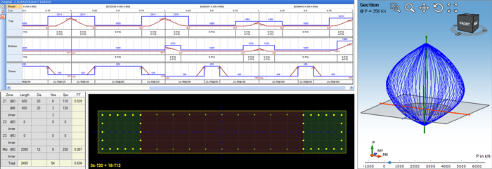
Columns are designed for axial force and biaxial moments. STAAD.Pro uses a sophisticated technique to construct 3D P-M surfaces for a particular cross section and reinforcement arrangement. These P-M surfaces are then used for the design. Due to the generic nature of the algorithm, any type of cross sections can be designed. An iterative procedure is used, starting with the minimum reinforcement, and then reinforcement is gradually increased until the capacity meets the demand. The reinforcements in columns are chosen such that these satisfy the minimum and maximum reinforcement percentage as well as spacing requirements. Ties of adequate size and spacing are provided to confine the longitudinal reinforcements. The minimum reinforcement ensures that the yield moment is greater than the cracking moment, which in turn ensures a ductile failure as opposed to a brittle one. The maximum reinforcement limit, on the other hand, prevents reinforcement congestion.
Ductility detailing requirements, if necessary, are also met by the software. Special confining to longitudinal reinforcement is provided as per 18.7.5 to prevent any buckling of longitudinal reinforcements, and also to ensure that the column has adequate axial strength. STAAD.Pro checks for minimum flexural strength of columns as per 18.7.3 so that the columns are stronger than the beams, thereby ensuring that total structural collapse does not happen due to yielding of columns. Shear strength at beam column joint is checked as per 18.8.4.1. Depending on the framing type, shear strength of the columns is checked as per 18.3.3 or 18.4.3.1. Although the software comes up with the bar arrangement, users have the flexibility to override that, as well as to change bar sizes and other design parameters on the fly to redesign any cross section.
Wall Design
Wall cross sections are designed following the same principles used for column design. Walls can be designed as both ductile and non-ductile, and users can control the reinforcement arrangement. Non-ductile walls are checked for in-plane shear as per section 11.5.4. Vertical and horizontal reinforcements satisfying the requirements of section 11.6 are provided for non-ductile walls. For ductile walls, the vertical and horizontal reinforcements and their spacing are provided as per 18.10.2.1. In-plane shear check for ductile walls are carried out as per section 18.10.4.1. The need to provide special boundary elements in walls is evaluated as per requirements laid out in section 18.10.6.
Generation of Reports and Drawings
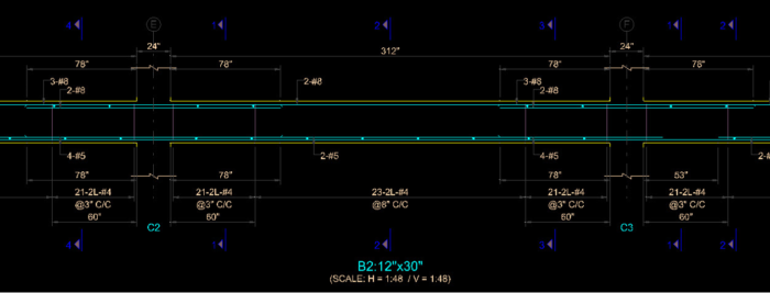
As mentioned earlier, STAAD.Pro is not only able to generate the design report, but can also generate bills of quantities, bar bending schedules, and detailed reinforcement drawings. Design reports can be presented in a summary format where the required and provided flexure and shear reinforcement data are presented in tables. Alternately, one can also generate a detailed design report including code references and calculations.
The bill of quantities can also be a summary report listing quantities of concrete, steel, shuttering, and cost. Alternately, one can also ask for a detailed bill of quantities which breaks up the reporting of quantities for each element of the structure. Drawings include elevations and sections with all reinforcement details. These drawings can be directly opened in MicroStation or can be saved as dxf, which can then be opened in any CAD package for further detailing, if required.
STAAD in Action
The STAAD products have played a key role in the analysis and design of many iconic concrete structures around the world. The K10 Grand office building designed by Vyom Consultants is one such building. The 12-story structure features a unique shape, which required use of inclined columns on several floors, and an open entrance foyer on the first level, which required long cantilever spans and complicated the seismic design. Using STAAD structural analysis and design software from Bentley, Vyom Consultants was able to investigate several design iterations and design all concrete components within an aggressive project schedule.
“As all the design aspects needed a lot of iterations, designing and analyzing using STAAD reduced the time to a great extent. With the help of STAAD, we were able to complete the entire building design with drawings within one month.”
– Vyom Consultants
K10 Grand Designed by Vyom Consultants
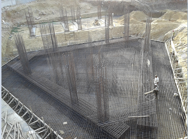
Raft Foundation Under Construction
Learn more about STAAD and RAM with Bentley’s eStore:
Attend the webinar series: Register here.
Discover the Reinforced Concrete Design with STAAD and RAM series featuring blogs and webinars.
For the price and the amount of Keys included in RAM Virtuoso Subscription, please visit this page.
Want to learn more about what STAAD and RAM can do for you? Don’t hesitate to contact our structural experts. We are happy to help.

