This blog is a part of the series: Your Guide for Soil Improvement with PLAXIS
Soil improvement is a critical process in geotechnical engineering, aimed at modifying soil properties to enhance performance. This technique is commonly used to increase load-bearing capacity, control settlement, and reduce the potential for liquefaction. PLAXIS, a finite element analysis software, is extensively used for modelling such improvements, especially column-based techniques.
The primary goals of column-based soil improvement include:
- Controlling settlement: Managing vertical displacement to ensure the stability and serviceability of structures.
- Enhancing load-bearing capacity: Strengthening soil to handle larger loads.
- Reducing liquefaction potential: Minimizing the risk of soil turning liquid under seismic activity or heavy vibrations.
Column-based Soil Reinforcement
Column-based reinforcement involves inserting rigid or flexible columns into the soil to enhance its properties. PLAXIS can model several reinforcement techniques, including:
- Stone columns
- Sand compaction piles
- Micropiling and rigid inclusions
- Jet grouting
These techniques vary in terms of soil displacement and the type of material used for reinforcement. For instance, stone columns displace soil, while rigid inclusions do not.
Modelling Techniques in PLAXIS
PLAXIS provides various approaches to model column-based reinforcement:
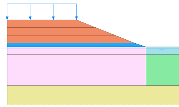
- Homogeneous block 2D model: This simplest method requires calibrating the equivalent stiffness of the block. It provides reasonable overall settlement behaviour but does not compute structural forces in the columns (see Figure 1).
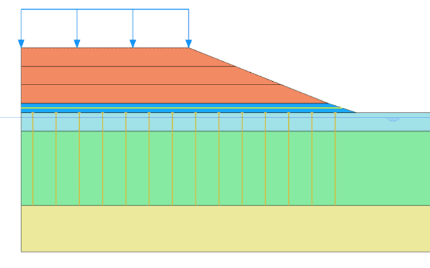
- Plate element 2D model: Incorporates a transfer plate to improve force transfer mechanisms. While structural forces can be accounted for, dynamic behaviours like punching are not well captured (See Figure 2).
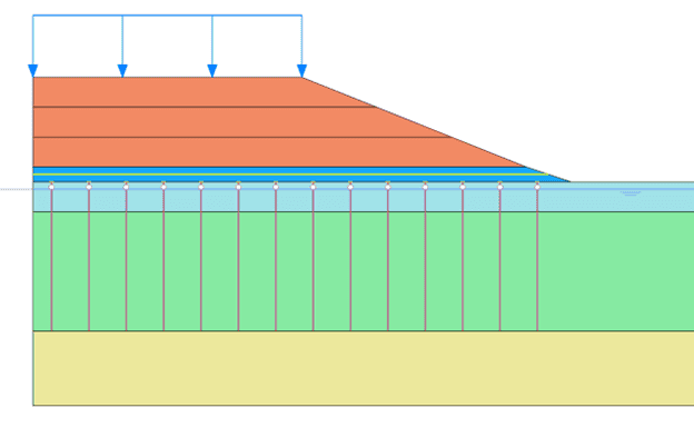
- Embedded beam 2D model: More complex than the plate model, this allows for end-bearing specification and calibrating interface stiffness. It is often used with a top transfer plate for ensuring a proper transfer force mechanism at reinforcement head and avoiding the possible appearance of unrealistic punching-in mechanisms within the mattress (see Figure 3).
Figure 1: Homogeneous block 2D model
Figure 2: Plate element 2D model
Figure 3: Embedded beam 2D model
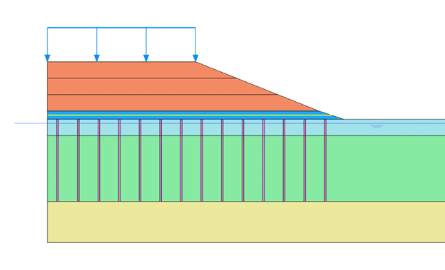
Figure 4: Continuum element 2D model
Figure 5: Continuum element 3D model
- Continuum elements 2D model: The model treats stone columns as thick walls within the soil mass (see Figure 4). There are two equivalence strategies used to adjust the model parameters:
- Wall thickness equals stone column diameter: This option directly matches the physical diameter of the stone columns with the model’s wall thickness. However, this approach often requires modifications to the stiffness to account for the spacing between columns.
- Wall stiffness equals column stiffness: In this approach, wall thickness is adjusted to ensure that the stiffness of the wall matches that of the stone columns. This ensures that the load-carrying capacity of the columns is accurately represented within the model.
The continuum elements 2D model is especially useful for evaluating ultimate limit states (ULS), where the development of plastic strains in the stone columns is of significant interest. While 2D modelling provides a simplified view compared to full 3D simulations, it is computationally efficient and can deliver reliable results for many engineering applications.
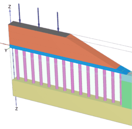
- Continuum elements 3D model: The 3D model in PLAXIS offers a more detailed and accurate approach to modelling column-based soil improvement compared to 2D methods. It represents the true geometry of the system, allowing engineers to capture the behaviour of reinforced soil and columns under more complex and realistic conditions (see Figure 5).
Unit Cell Concept for Calibration of 2D Plane Strain Models
The unit cell concept is critical for bridging the gap between simplified 2D models and more complex 3D behaviour in stone column and rigid inclusion applications. By carefully calibrating stiffness and interface properties using this approach, engineers can ensure that their 2D plane strain models accurately predict real-world performance, making it an efficient and effective method for designing soil improvement solutions.
- Purpose of the unit cell concept
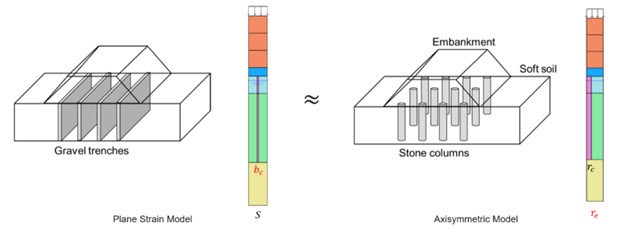
The unit cell approach allows engineers to model a small, representative section of the entire soil-column system, which can then be used to calibrate a larger 2D plane strain model. By focusing on this smaller section, engineers can fine-tune parameters like stiffness, interface behaviour, and load transfer mechanisms to ensure that the model’s predictions match real-world behaviour.
In the context of stone columns and rigid inclusions, the unit cell represents a single column and the surrounding soil, capturing the interaction between these two components (see Figure 6). It’s an effective way to simulate load distribution and settlement behaviour without needing to model the entire structure in 3D, which would require significantly more computational resources.
- Calibration process
The calibration process for a 2D plane strain model using the unit cell concept involves several steps:
- Define the influence zone: The influence zone represents the area of soil affected by a single stone column or rigid inclusion. Common configurations include triangular, square, and hexagonal patterns of stone columns or rigid inclusions, each affecting the surrounding soil in different ways.
- Use of axisymmetric models: In the unit cell approach, an axisymmetric model is often used as a reference for calibration. Axisymmetric models provide a more accurate representation of the stone column or rigid inclusion behaviour, since they can account for radial symmetry. By comparing the axisymmetric results to the 2D plane strain model, engineers can adjust parameters in the 2D model to ensure consistency.
- Calibration Process
Stone Columns: Calibration focuses on the stiffness or thickness of the stone column strip to replicate the geometric and load-carrying behaviour accurately.
Rigid Inclusions: Calibration requires more detailed adjustments, including load transfer at rigid inclusion head, interface stiffness factors that obtain the correct evolution of normal forces within the inclusions, and base stiffness/tip resistance. These factors are necessary to simulate the rigid inclusion’s role in structural support and differential settlement mitigation.
Figure 6: Unit Cell Approach
Conclusion
Column-based soil improvement is an essential aspect of modern geotechnical engineering. Numerical modelling through PLAXIS enables engineers to simulate various soil reinforcement techniques, from stone columns to rigid inclusions, ensuring that designs are safe, effective, and efficient. By leveraging tools like 2D and 3D modelling, geotechnical professionals can predict behaviour under different load conditions, optimize designs, and ensure structural integrity in challenging soil conditions.
As numerical modelling tools advance, the future of soil improvement techniques will continue to evolve, offering more precise and robust solutions for geotechnical engineering challenges.

