Our OpenTower Team is excited to announce the availability of OpenTower Designer CONNECT Edition (Metric) 3.1! [Version:10.03.01.88]
This new release contains powerful capabilities to support the much awaited seamless full integration with MStower jobs and text editing facilities. It will enable all the MStower users to migrate their jobs in OpenTower Designer and take advantage of the new design codes like TIA 222H, EN 1993, Foundation Design and export them to iModel as well, which are absent in MStower.
Here is the complete list of what’s new in Update 3.1:
Orientation
Tower Orientation
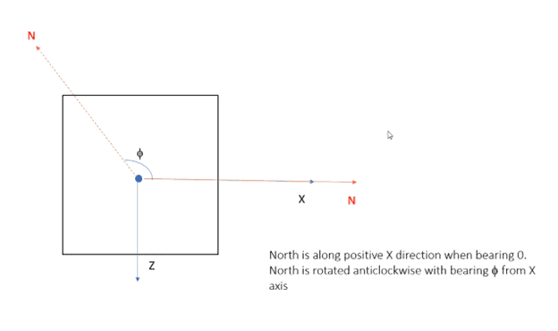
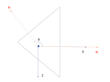
The orientation of tower and bearing is modified and aligned as per MStower convention.
Orientation Of Discrete Ancillaries
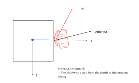
The Ancillaries are oriented with respect to the local axis satisfying the global azimuth angle as the clockwise angle from the North to the Antenna Vector.
The above orientation will establish an identical setup of tower and antenna orientation between OpenTower Designer and MStower in terms of visualization as well as wind load calculation.
Import & Export
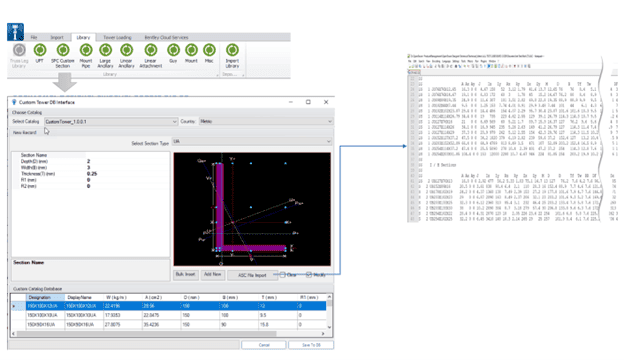
MStower Section Library
Utility is provided to import the Section Library (.ASC) from MStower. This will ensure that OpenTower Section database is synchronized with a MStower Section library file.
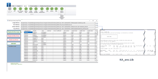
MStower Ancillary and Guy Library
Utility is enhanced to import the Ancillary Libraries from MStower. This will ensure that OpenTower Ancillary databases (Large, Linear and Guy) are synchronized with a MStower ancillary references.
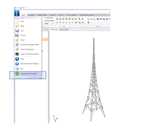
Export to OTXML
OpenTower designer file can now be exported to an OTXML format, so that it can easily be consumed and create an iModel through OpenTower iQ.
Editor
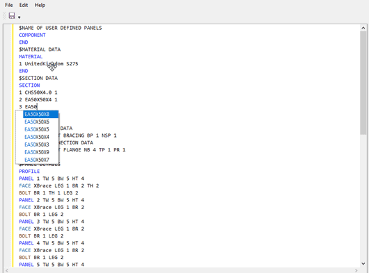
Quick Section Editor
A text editor like the (MStower .td Editor) is now available for managing the following:
- Section Modification
- UPT Section Modification
- Managing Face, Hip and Plan bracing
- Managing Panel Bracing ( like DM, DLM , DRM etc. )
- Associate UDP
- Managing Connection (other than Base Plate)
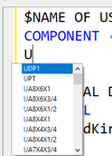
The editor is enabled with intellisense like list of Section, Material Group etc. which will help the user to choose the desire entity (not to memorize).
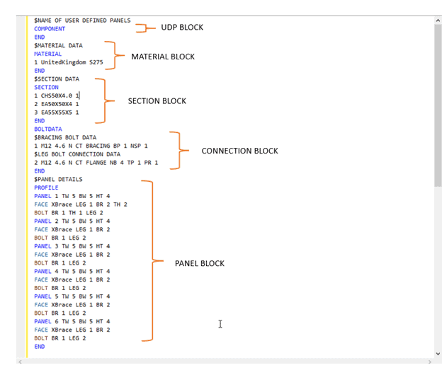
UDP Block:
The block starts after the COMPONENT keyword. Any UDP (imported from an MStower file or created from the UDP editor) can be assigned. The IntelliSense will help you to pick up any UDP, already saved in the model.
A UDP defined in the UDP block can be assigned to a Panel if their geometric dimensions (height, width, and depth) are identical.
To assign a UDP you need to start with “@” followed by the UDP name after the “FACE “keyword.
Material Block:
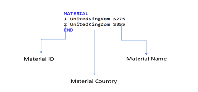
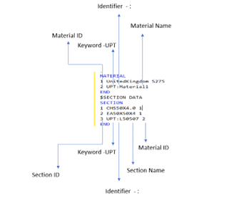
The Material Block starts with the MATERIAL keyword. A unique Material is defined with the combination of a Material ID, a Material Country, and a Material Name.
Each Material is associated with a Particular section through Material ID.
Section Block:
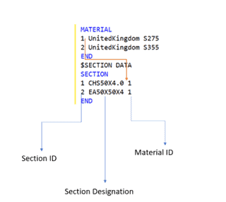
The Section Block starts with the SECTION keyword. A unique Section is defined with the combination of a Section ID, a Section Designation, and a Material ID.
Each Section is associated with a Member class (like Leg, Bracing, Redundant, etc.) through the section ID.
UPT Members and Section:
Any UPT section or material created in the model can be defined within the section and material block respectively. To differentiate a UPT type the keyword “UPT” has to be used followed by a “:” as an identifier.
Connection Block:
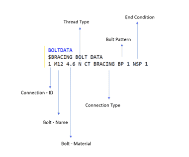
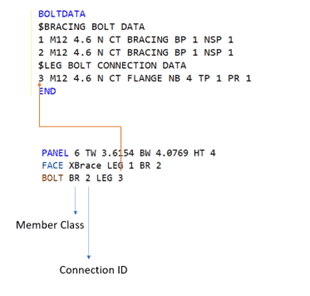
The Connection Block starts with the BOLTDATA keyword. A connection type is either Leg Connection or Bracing Connection. For all the Bracing connections (for member class apart from Leg), they are applicable. They are identified as the keyword CT BRACING. Other keywords for a unique Connection are shown in the image below. The different Types of Leg Connections are FLANGE, SSLEEVE, and SPLICE.
Bracing Connection Example
The association of a connection with a member class is achieved through the Connection-ID.
Bracing Pattern:
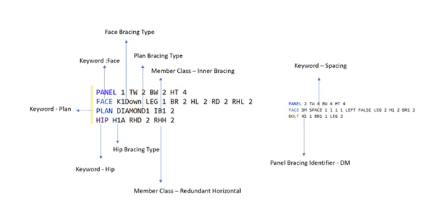
You can assign any Bracing pattern ( Face , Hip , Plan , Panel or UDP ) for a particular Panel inside the Panel Block.
Caveat and Information:
- An editor is a tool for quickly changing and assigning sections, materials, connection information, and bracing patterns. The geometric dimension of any panel is for reference. You can’t edit those items in this tool.
- It is advisable not to change any existing item for Material, Section, and connection. Append a new ID and assign that to the member class.
- If there is an error in processing the Editor text, there will be a red symbol, beside the unprocessed line item.
- Use the section detail page for changes related to base-plate connection type, Design Parameters, and unidentical Bays or Faces.
Wind and Design Code
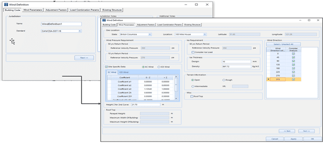
CSA 37
OpenTower Designer is now capable of doing design and load generation as referred in National Standard of Canada CSA- S37-18.
Others
Load and Analysis
- Large and Linear Appurtenance loading is now aligned with MStower methodology, and the intermediate results are produced for easy understanding.
- Reaction forces (Design Reaction Forces) for primary load cases considering the impact of Gen Factor is now available in a csv format for Lattice tower (Euro Code).
Design
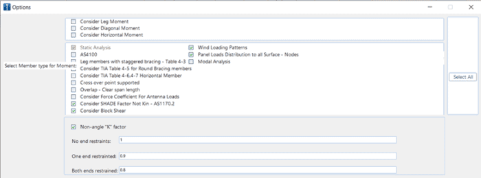
- Slenderness logic updated for codes TIA 222F, TIA222G, TIA222H, AS3995 and CAN/CSA-S37with “Non-angle “K” factor” logic to align with MStower methodology.
- Option for design of angle section as per AS 4100 code.
- TIA table 4-5, 4-6, 4-7 logic provided as option for Australian code.
- Block shear is option for connection design.
- Design of tension rupture and connection bearing strength as per BS 8100-3 code provided as an option for Euro code.
- Practical consideration of K=0.80 for directly welded tubes and rods provided as option for Euro code.
Operation
- Active scenario is now highlighted with a green icon and non-active scenarios with a gray icon for better understanding.
For more information about OpenTower Designer contact us at [email protected] or visit https://en.virtuosity.com/opentower-designer/ to request a demo or purchase.

