
Modelers today often don’t realize how easy they have it. Digital terrain models, GIS, model builders, and other tools have made model creation very easy, even for huge models. It wasn’t always like that.
Solving pipe network equations is very difficult.
In any reasonably sized system, it is necessary to solve thousands of simultaneous non-linear equations. Before computers came along, simplifications and approximations were needed to make the solutions possible. The Hardy-Cross method in the 1930s provided a systematic approach for solving problems, but engineers were still limited. This blog looks at some of the tools that were used along the way to the technology we have today.
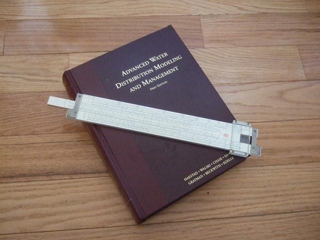
The most important tool was the slide rule. This used the concept that multiplication is really just adding logarithms. The slide rule does that elegantly. The slide rule also helped its users understand the problems. It could give you an answer of 61, but the user had to know whether it was 61, 6.1, 0.0061. Understanding order of magnitude was important and is often not appreciated today. Another feature was that there was no fake precision implied in the results. An answer of 0.61 was just that. It wasn’t 0.6147387 which is the kind of misleading precision that can come out of digital models or SCADA displays.
 Slide rule
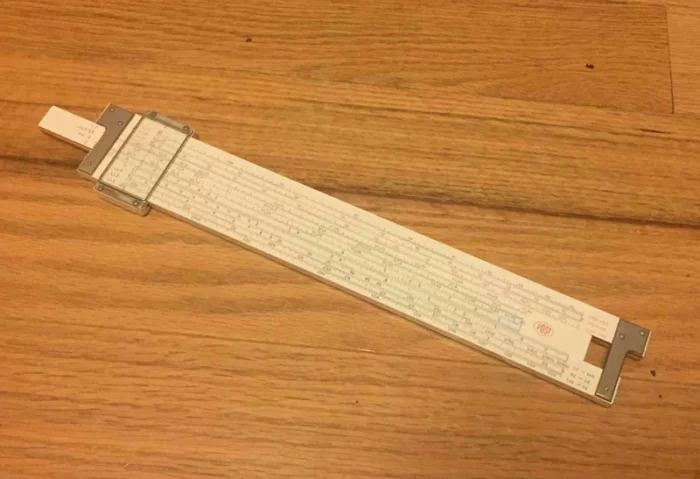 Slide rule
A slide rule can be a daunting tool, but the concept of a slide rule can be simplified, and special purpose slide rules arose to solve specific problems such as the Hazen-Williams equation. You didn’t need to understand the theory behind slide rules, but you could get the results quickly.
 Special purpose slide rules
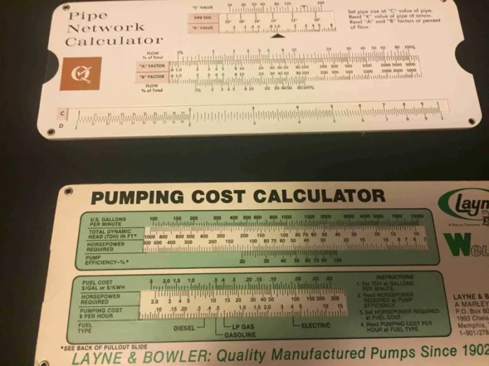 Special purpose slide rules
By the 1950s, digital computers had arrived, but how can a human get data into such machines? The interface was through punch cards or paper tapes. These devices had been invented much earlier, but they now became the gateway to computers. Holes punched in cards could mean the number 87 or be an instruction to add two numbers.
 Punch card (IBM card)
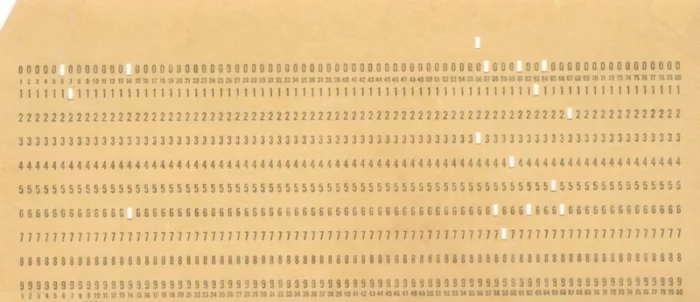 Punch card (IBM card)
But how did you determine the length of pipes because the length is a critical input to head loss calculations. An engineer’s scale was a critical tool for measuring those lengths.
 Engineer’s scale
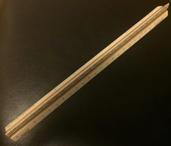 Engineer’s scale
However, not all pipes were straight, and a ruler doesn’t measure curved lines well. That’s where a miniature measuring wheel came in handy. An engineer could roll this along any pipe (straight or curved), and it would indicate the length on the sheet.
 Wheel
Wheel
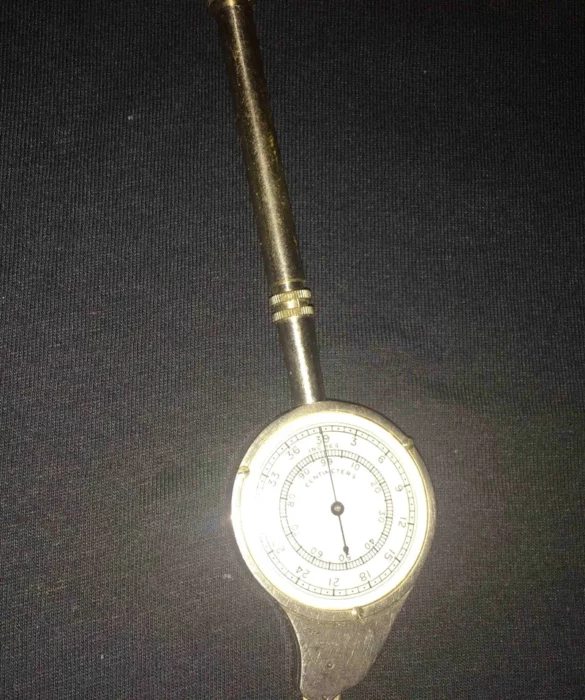 Wheel
WheelThis may not look too much like computer modeling to today’s generation, but in the past, a great deal of effort was required to obtain simple information like pipe length.
 Pipe length measurement
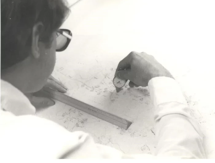 Pipe length measurement
What kind of mapping of systems was available? Usually, these were paper (or mylar) maps or as-built drawings. There was no GIS where the pipes “knew” their length. Sometimes these paper sources of truth had too little or too much information on them, such that finding the right data could be challenging.
 As built drawing
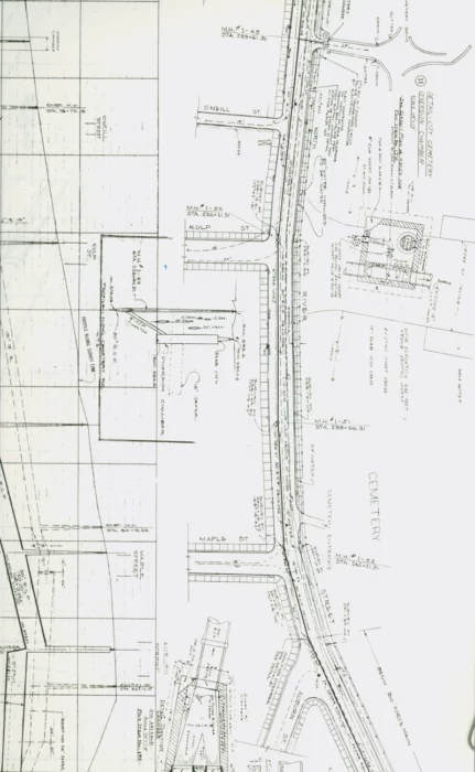 As built drawing
Eventually, paper maps gave way to CAD drawings but, at first, these were just essentially paper maps on a computer. It took some time to capture the lengths of pipes and other properties and serve them up to the engineer. Until them, it was still a matter of measuring properties from the maps.
 CAD map
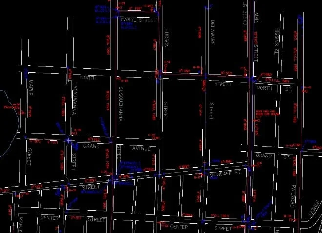 CAD map
One of the most tedious kinds of information to determine was elevations of nodes and other facilities. Usually this information was available in the form of contours on maps. The US Geological Survey maps were a good starting point, but their resolution left something to be desired. To find the elevation of a point feature, it was necessary to find the contours that lie on each side of the point and then interpolate the point’s position between the contours—a task that was both tedious and error prone. It was not until the arrival of digital terrain models that the pain from this task was relieved.
 Topo map
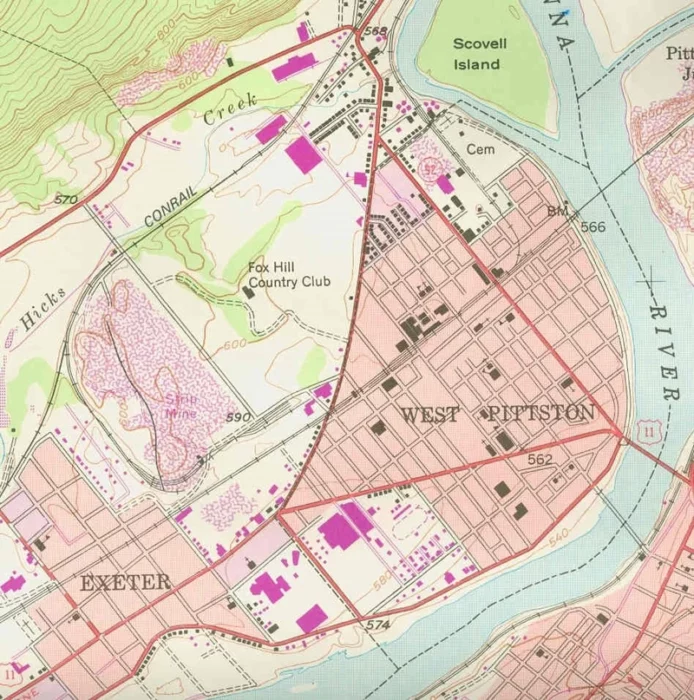 Topo map
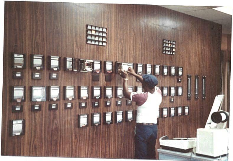
But data was needed to calibrate a model. Unlike today, where a modeler can download megabytes of time series pressure and flow data quickly, modelers were only provided paper, pen-and-ink charts. It was necessary to manually read each point off the chart to develop a time series. It wasn’t uncommon for these pens to dry up or blot at critical times. There were advantages to using these analog charts in that they could detect hydraulic transients which could be missed by typical SCADA with its discrete polling intervals.
 Paper chart
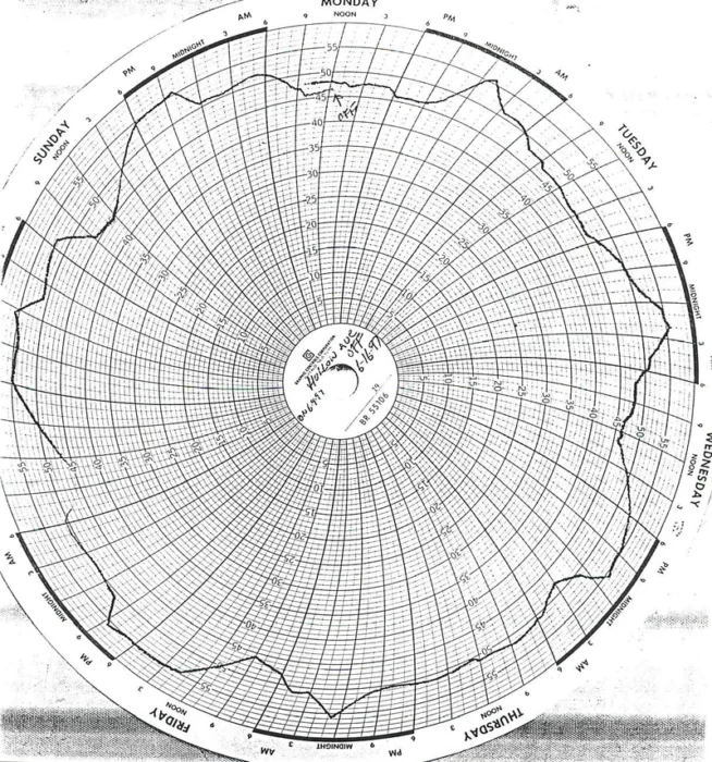 Paper chart
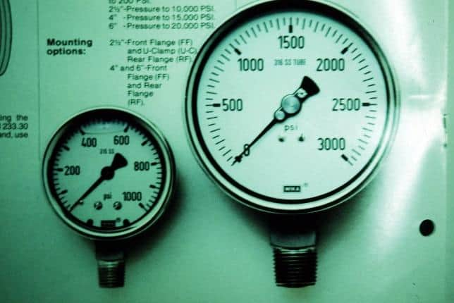
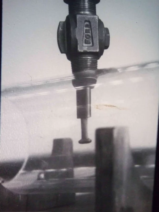
Obtaining flow data over time in pressure pipes was made possible using a Pitot rod developed by John Cole around 1900. But this device required excavating to the pipe and tapping it to insert the rod. However, it still remains a useful too although those individuals who know how to use it are becoming fewer.
 Pitot rod
 Pitot rod
In the not-too-distant past
Performing the hydraulic calculations whether manually or with early computers often took up a great deal of time within a planning or design study. There frequently was little time left to develop solutions. With today’s building models has become dramatically easier leaving more time to develop the best solution to the problem at hand, which is why hydraulic calculations are performed in the first place. Looking back at the technology that came before can help modelers appreciate the advances that have been made over the years.
Want to learn more from our resident water and wastewater expert?
Join the Dr. Tom Walski Newsletter today!