I didn’t get much response to the question I posed in a recent blog about the best placement of isolation valves. Either readers thought the question was too difficult or I would need to come up with more interesting blog topics.
The question was: Which of these valves would you install if you were designing a distribution system?
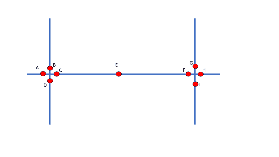
In my opinion, the correct answer is shown below and most readers who replied to my recent blog agreed with this.
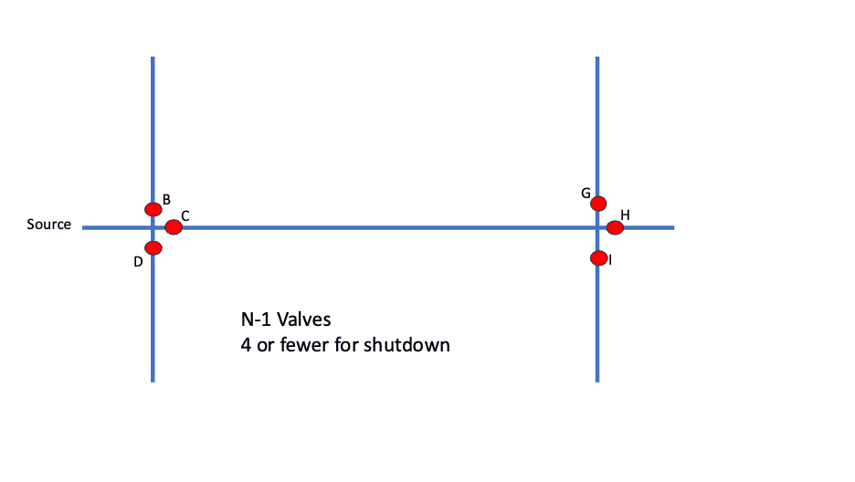
Why is this a good design? First, it uses N-1 valving which will give the lowest cost with a relatively simple shutdown using four or fewer valves. But why those six valves?
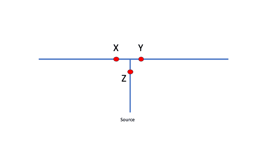
To understand, let’s go back to the extreme case of a tree-shaped system as shown below. If there is a need for a shutdown in either the X or Y branch, you only need to shut down the individual branch. If you close Z, you shut down both branches. So, if you want to use N-1 valving, you will eliminate Z.
We can agree that this is a good solution for a tree-shaped system, but does the design make sense for a looped system? It does.
My basic logic is that you want to get flow into the cross or tee intersection and then close only the outgoing pipe, which needs to be shut down without affecting the others.
So much for the specific question … Ideally, I would like to see that state standards would reflect this logic by requiring at least N-1 valves at each intersection and that the valve on the predominant inflow pipe to an intersection is the one that can be eliminated. That would hold for distribution mains.
For large transmission mains, you should install fewer isolation valves on the big pipes for cost reasons, but every branch off the transmission main would need to have an isolation valve close to the large main.
The concept of evaluating valving based on the number of valves at an intersection is valuable but it has never had a name. In a brainstorming session with my colleague, Enrico Creaco, we concluded that discussing the number of valves at an intersection should be called the “valve concentration at an intersection” or “valve concentration” for short. So, if you’re discussing a four-way intersection with three valves, the valve concentration would be three or N-1 if you are talking about valving in general.
I looked through a few more state standards that give engineers a good bit of leeway in deciding where to locate valves.
The Texas rules state, “The system shall be provided with sufficient valves and blowoffs so that necessary repairs can be made without undue interruption of service over any considerable area and for flushing the system. The engineering report shall establish criteria for this design.”
While the Washington design manual says, “Designers should place enough valves to minimize the number of customers out of service when the water system needs to isolate a location for maintenance, repair, replacement, or additions. Spacing of distribution system isolation valves should be 800 feet or less (AWWA 2008) unless the grid geometry or low housing density justify greater spacing.”
These provide the design engineer with a lot of flexibility in placing valves.
So, before folks get tired of this topic, I’ll move on to other topics. Stay tuned.
References
Texas Commission on Environmental Quality (2019) “Rules and Regulations for Public Water Systems”.
Washington State (2020) “Water System Design Manual DOH Pub 331-123”.
If you want to contact me (Tom), you can email [email protected].