SewerGEMS is capable of automatically sizing pipes, manholes and hydraulic structures in addition to determining bottom elevations. In addition to being able to dimension according to various restrictions defined by users during automated sizing, such as permitted slope ranges, covering speed and tensile tension.
Using the rational solver for gradually varying flows or the convex solver for gradually varying flows in SewerGEMS/StormCAD, you will be able to size various elements of a network from a single pipe to an entire system. The design algorithm attempts to minimize excavation, which is typically the largest CAPEX expense for sewage collection and transportation networks.
SewerGEMS can automatically design the inlet width of culverts in any element of the network for a given catchment basin. In summary, the steps to configure this feature are:
- First configure the model for analysis;
- Specify the elements to be dimensioned and the available diameters;
- Indicate the constraints on sizing;
- Run the automated sizing, defining the scenario calculation type (found in the calculation options) by defining “design” in place of “Analysis”.
Defining the elements to be dimensioned
Through it you can modify the restrictions for just one element. All you need to do is create local restrictions by activating the “Specify Local Pipe (inlet)” option in the attribute table associated with this element.
In the automated sizing routine, you define the shape and material for all conduits, and you must define initial dimensions. The automated design routine will adjust the appropriate section dimensions according to the tube catalog enabled for the design. If you want to ‘preserve’ the dimension of certain sections so that the design routine does not change them, you can choose “false” for “design conduit?” in the properties of the tube attributes table.
Standard sizing restrictions
As mentioned previously, pipe diameters, bottom dimensions, node structures and culverts can all be designed with the same set of design constraints, or even individually through the option to adjust these values individually for each pipe or structure.
The window for defining sizing restrictions has the following tabs:
- Gravity tubes
- Us
- Manholes
gravity pipe flap
In the gravity tubes tab, it is possible to define the default restrictions, which will be applied to the tube design during the “Design” sizing mode. Within this tab there are two configuration options:
- Standard Constraints
- Extended options for Sizing
Manhole Flap
This tab allows you to define specifications and design restrictions for the culverts
Default restrictions section
Here it is possible to specify maximum and minimum values for speed, cover, slope and tensile stress as standard constraints to be met when sizing gravity pipes.
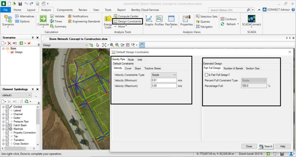
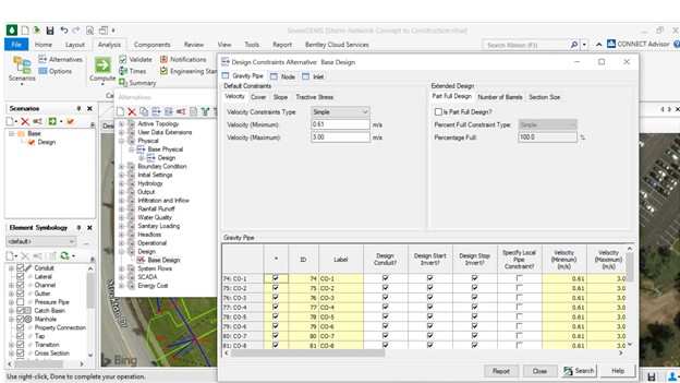
Extended sizing options section
In this section it is possible to specify some additional options in the alternatives manager. Gravity pipes must be designed to operate partially full, while forced pipes must operate completely full. In this way, for gravity tubes, when selecting the “Partialy Full Design” option, it is possible to specify the filling limit of the gravity tube cross-section for sizing as a constant (Simple) or a tabular list (depending on of the pipe elevation). You can also allow multiple parallel pipe barrels or limit the maximum section size by specifying the maximum rise. It is also possible to allow the definition of tubes in parallel or limit the maximum height of the section defining by the maximum elevation
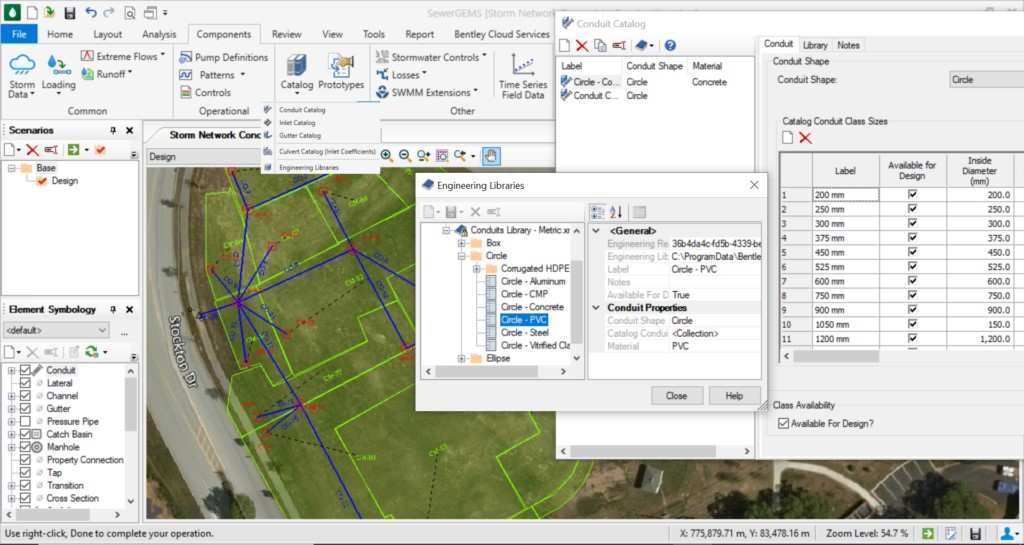
Pipes and Manholes Catalog
During automatic sizing, the software will use the sizes and materials of only the pipes and manholes listed in the catalogs, which can also serve as an alternative way to impose restrictions on the model. You can also create your own catalog by placing the models, materials and diameters you want to use in your projects.
The ultimate goal of automating sizing is to obtain a project that meets the given criteria, saving time by allowing more alternatives to be evaluated in less time.
The optimizer will select pipe diameters and bottom dimensions based on the constraints, input data, and sizing options provided. It is possible that the initial sizing proposal, which has a gentler slope and less coverage, could meet the criteria for a specific conduit. However, these options, when propagated to the network or downstream system, produce results that are not within the prescribed criteria.
Therefore, the modeler must always review any automated project and must make the necessary changes to improve the system. Automated sizing generates proposals and solutions based on constraints for the entire system and the solver tries to find the most appropriate solution. However, the final design must take the engineer’s judgment into account.