SewerGEMS can automatically size conduits, set node invert elevations. It also determines the size of inlets to pass a Sanitary/Storm design while meeting user-specified constraints in automated design. It allows you to design many parts of the sewer network from a single pipe size to the entire system. Using SewerCAD/StormCAD engine using the GVF Rational solver in CivilStorm and using the GVF Rational or GVF Convex solver.
Pipes and structures designed to consider several constraints such as allowable ranges of slope, velocity, and cover. The design algorithm attempts to minimize excavation, which is typically the most expensive part of installing sewer piping and structures.
SewerGEMS can automatically design the inlet opening length for the inlet at any catch basin element in the network.
You can modify the constraints for just an individual element. You just need to check- Specify Local Pipe (Inlet) Constraints box associated with that element.
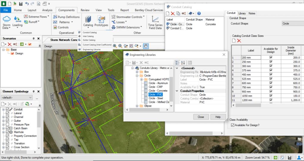
In order to use automated design, you must set all conduits to the correct shape and material, as well as set an initial conduit size. The automated design routine will select appropriate section sizes from the conduit catalog. If you want to ‘preserve’ certain conduits so that the design routine does not change them, you can choose “false” for “design conduit?” in the conduit properties.
To use this feature: set up the model for analysis first. Specify the elements which need to be sized and the sizes available for use in the design. Then indicate the constraints which needs to satisfy. And set the scenario’s Calculation Type (found in the calculation options) to Design as opposed to Analysis.
Default Design Constraints
Pipe diameters, invert elevations, node structures, and inlets can be all designed with the same set of design constraints. You also have the option to adjust these values individually for each pipe or structure.
The Default Design Constraints dialog has three following tabs:
- Gravity Pipe
- Node
- Inlet
Gravity Pipe Tab
The Gravity Pipe tab allows you to enter default constraints, which used for the design of pipes when doing a calculation in design mode. The dialog has two following sections:
- Default Constraints
- Extended Design
Default Constraints Section
You can specify here Velocity, Cover, Slope and Tractive Stress as default constraints which used for the design of gravity pipes.
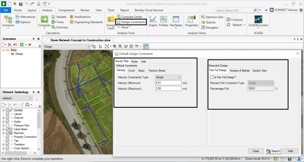
Fig.1. Default Design Constraints
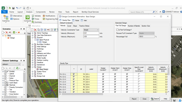
Fig. 2. Design Alternative
Extended Design Section
You can specify some additional options under the Extended Design portion of the alternative manager. Sometimes the pipes must be designed to carry the design flow at less than 100% full (100% Full -default). You can check Partly Full Design. And also specify the design percent as either a constant (Simple) or a tabular list (function of conduit rise). You can also allow for multiple parallel pipe barrels or limit the maximum section size by specifying maximum rise.
- Default in Sag Design Constraints Section
- Default on Grade Design Constraints
Conduit and Inlet Catalog
During Automatic Design, the software suggests only conduit and inlet types contained within the Conduit and Inlet Catalogs. You may also create new Templates and use those in future models.
The ultimate objective of the automated design is to an overall balanced design as per the criteria given. It will select pipe sizes and pipe invert elevations based on the input provided. It could be possible that while having a milder slope & less cover might fulfill the criteria for a particular conduit. But the effect of the same could be propagated downstream producing results which are not falling within the prescribed criteria. But The modeler should always review any automated design, and should make any changes required to improve the system.
Constraint based design is for the entire system and the solver tries to find the best fit solution. Nevertheless, the final design should be as per the engineer’s judgement.
Automated Design for Storm/Sanitary Design
 Best-selling Water Resources Textbook
 Best-selling Water Resources Textbook
Computer Applications in Hydraulic Engineering
This fully updated 9th edition textbook is available for download! Ideal for engineers and students in hydraulics and hydrology, offering theory and real-world applications with problem-solving and modeling exercises featuring OpenFlows WaterGEMS, HAMMER, SewerGEMS, SewerCAD, PondPack, StormCAD, FlowMaster and CulvertMaster.