Pumps are great for lifting water uphill. But the uphill slope from the pump may not be uniform over the length of the pipe (force main, rising main). The elevation of the terminal discharge point may only be slightly higher than the water source. However, if there are one or more hills along the way, it is necessary for the flow to get over the hills.
Pumping Over High Points
Modeling the pump and pipe as a single pipe without accounting for intermediate high points can yield some misleading results. It will usually show a result as the profile below.
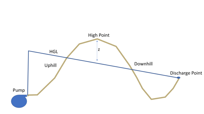
Operation as siphon
Will the pipeline shown above work? The figure shows the pipeline operating as a siphon. It may work if z is very small. In areas where the pipe is above the hydraulic grade line (HGL), the pressures are negative, something that is not allowed in potable water distribution piping. But there are some problems with this design. First, is the flow sufficiently large and the downhill pipe slope sufficiently flat that the pipe will flow full? If the downhill slope is small or the flows low, the pipe may never reach full flow, and the siphon will not be established. Second, if z is greater than 32 ft (9.2 m), the liquid water will be below the vapor pressure of water, and the siphon will never form. Third, even if the siphon works, eventually gases will collect at the high point and reduce the pipe capacity. This design is generally not recommended.
The key to this design is to install (and maintain) an air release/vacuum breaker valve at the high point. Such a valve is reliable in clean water systems but needs a lot of attention in wastewater force mains because fats, oils, and grease can accumulate in the valve and block it. For hydraulic calculations, it’s generally safe to assume the air valve is well maintained.
So, how does this piping over the hill work? If the pump has been off for a non-trivial length of time, the downhill sloping portion of the pipe will drain, but water will be found in the uphill pipe, and any pipes below the discharge point as shown below.
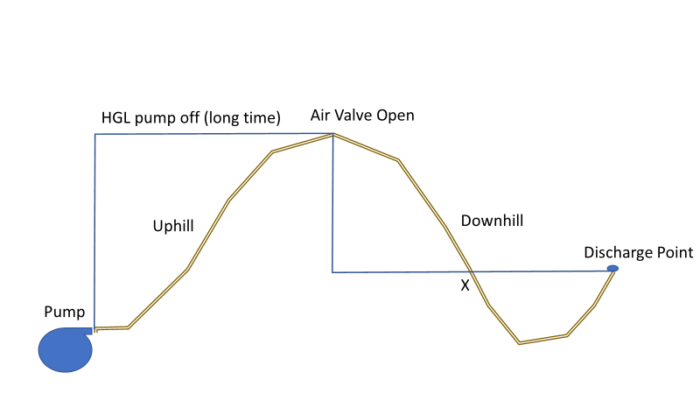
HGL when pump off
When the pump is turned on, it gradually fills the downhill section. When the runtime is short, the flow is low, and the downhill slope is large, it may never fill the downhill pipe. The places where the HGL is below the pipe are those that are flowing partly full.
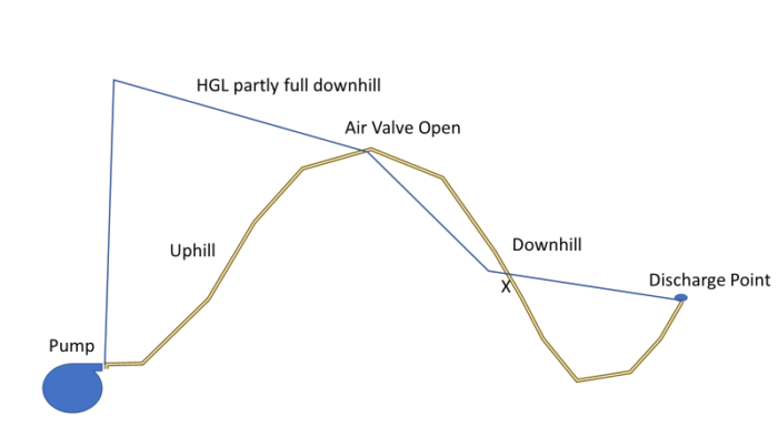
Pipe filling
Eventually, if the flow is sufficiently large and the slope is mild, the downhill pipe will fill, and the HGL will be above the air valve, which will close.
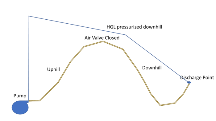
Pipe full
Pump selection, in this case, can be tricky. There will be a different system head curves depending on whether the pump is pumping to the top of the hill (i.e. downhill pipe filling) versus. the case once the pipeline is full. Any pump selection needs to consider both cases.
For example, consider a pipeline with a high point. If it is modeled as completely full, the system head curve is based on the entire pipeline. If the pipeline is filling, it is modeled only from the pump to the high point (set the system downstream of the high point to “Inactive” and place a reservoir at the high point for that scenario. The two system head curves and the pump curve may be as shown below.
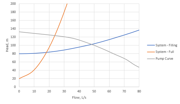
System Head Curves
The blue system head curve represents the case where the pipe is filling. It has a high static head. The orange curve shows a much steeper slope because, in this case, the length of pipe causing friction head loss is very long compared with the length to the high point. The gray line is the pump head curve. The flow from the pump will be on the order of 50 L/s as the downhill pipe fills, but will drop to about 25 L/s once the pipe is full. It is difficult to find a pump that will run efficiently over that range of flows. This will not always be the case, as each pipeline is different.
There are also implications for transient analysis with HAMMER. Transient calculations are based on full pipe flow. Therefore, while the pump is filling, it is only necessary to model from the suction source to the high point until the downhill slope section becomes full. Once it is full, it is necessary to model the entire pipeline.
If you want to look up past blogs, go to https://blog.bentley.com/category/hydraulics-and-hydrology/.
If you want to contact me (Tom), you can email tom.walski@bentley.com.
Want to learn more from our resident water and wastewater expert? Join the Dr. Tom Walski Newsletter today!

