I often title my blogs with a question that I’m very happy to try to answer. “What’s the Capacity of That Pipe?” is not one of those questions. Unless you make some simplifying assumptions such as “The pipe is flowing at normal depth” or “The full pipe velocity is 5 ft/s,” the real answer is elusive. I usually respond with a litany of questions, including “Why are you calculating this?” and “What assumptions are you willing to make?”
The most important distinction is whether the pipe is designed to flow full, like a water distribution pipe, or a sewer force main, as opposed to a gravity sanitary, combined, or storm sewer. Therefore, there is a two-part answer to the question in this blog but they both go back to this simple equation:
Q = A V
Where Q = flow (and in this case capacity), A is the cross-sectional area occupied by the flow, and V is the velocity.
Such a little equation for such a big concept.
Regulatory/administrative people like to treat the capacity as a fixed number. If someone says the capacity is 500 gpm, and you want approval to use the pipe to move 499 gpm, you are fine. However, if you should ask for approval to transport 501 gpm, then the pipe is inadequate and cannot be approved. Anyone who understands hydraulics knows that such an interpretation doesn’t make sense, but some people insist on a Boolean yes/no answer. There are so many uncertainties such as nominal vs. actual diameter and pipe roughness that can affect the pipe, not just the size. For example, do you have a flow meter that can accurately measure the difference between a 499- and a 501-gpm flow? Another layer to the question is whether this is about a single pipeline or a system.
Let’s look at each type of flow.
Full Pipe Pressure Flow
For full pipe flow, there is no problem, determining A. It is simply:
A = π D2/4
Where D is the diameter (nominal, actual internal, other?).
On the other hand, the value of V is pretty arbitrary. For pipe sizing in design, some engineers are satisfied using a fixed number such as 5, 8, 10 ft/s. However, when I look behind these values, I couldn’t find any solid justification for these peak velocities other than that the numbers are reasonable. Too high of a velocity, and the pressure at the end of the system drops and the effects of transients become more critical. Too low of a velocity, and the cost of piping increases.
Seldom are you working with a single pipe. You are more likely to work within a pressure zone rather than a single pipe. If the flow is going into a small pressure zone, you can tolerate more head loss and a high velocity, but if the water must go across a very large pressure zone, you’ll want a lower head loss gradient and a lower target velocity.
If you are trying to determine the capacity of a distribution system and not just a single pipe, you can load a model with a target demand scenario and check if the pressures are adequate. Then you can increase the demands until the pressures become unacceptable. (That approach assumes the spatial distribution of demands increases uniformly as you increase demand, or you can account for changing spatial demand patterns in some other way.)
Also, it is usually possible to modify the hydraulic grade at the source by adding pumping capacity or increasing a control valve setting within reason. You can squeeze a bit more capacity from your system this way.
Gravity – Partly Full Pipes
For gravity pipes, the value of A is no longer a constant, but if you are interested in capacity, you will be mostly interested in conditions when the pipe is full. That is usually determined by assuming a normal depth with a full pipe and applying Manning’s equation. Bentley’s FlowMaster is very good for this type of calculation. Just plot rise/diameter vs. flow and look for the maximum.
One counterintuitive point in partly full pipes is that maximum flow in a circular pipe occurs not when the pipe is full but when it is about 90-95% full, as shown in the figure below. That is because as the water surface approaches the pipe crown, the hydraulic radius (A/P) decreases because the wetted perimeter (P) increases faster than the flow area (A). Therefore, the friction increases and the velocity decreases as the pipe fills.
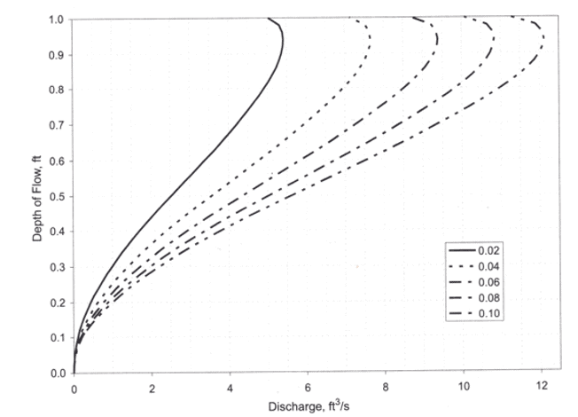
From Bentley Systems, 2005, Wastewater Collection Systems Modeling and Design, Bentley Systems, Exton, PA.
Some regulators/standards setters like to include a safety factor when they determine the capacity. For example, some may stipulate that the capacity is the flow when the pipe is 75% full, and in one case I saw, 50% full. The definition of “capacity” in a sewer appears to be a local decision.
Just as you can increase the capacity of a pressure pipe by pumping, it’s possible to increase the nominal capacity of a gravity pipe by allowing it to be surcharged. That could work if there is a short stretch of a fairly flat pipe along a pipeline with an overall adequate slope.
Summary
So, if anyone demands to know what’s the capacity of a certain pipe, there can be a wide range of “correct” answers. Just don’t tell that person to “Ask Tom.”
Read more of Tom’s blogs here, and you can contact him at [email protected].
Want to learn more from our resident water and wastewater expert? Join the Dr. Tom Walski Newsletter today!