One of the most important inputs to transient analysis is the speed of the pressure wave (called celerity) moving through the pipes. The speed depends on the fluid properties and pipe properties and has a significant impact on the magnitude of the transient pressure wave and the speed at which it moves through the pipes.
Unlike many other pipe properties like diameters and length, and fluid properties like density, wave speed is not something you can find in a GIS or a handbook.
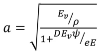
Where a = wave speed, m/s; Ev = bulk modulus of elasticity of liquid, Pa; E = Young’s modulus for pipe material, Pa; ρ = fluid density, kg/m3; e = wall thickness, mm; D = pipe diameter, mm; ψ = pipe support factor.
Basically, wave speed is controlled by the elasticity of the pipe wall and compressibility of the fluid.
Most of these inputs are known, and libraries of these values are provided in the HAMMER wave speed calculator for a variety of pipe materials and fluids. Tables are also provided in the Bentley book, Advance Water Distribution Modeling and Management. The most uncertain is the pipe support factor which depends on Poisson’s ratio and the nature by which the pipe is supported from axial motion. They can be given by
Ψ = 1, for a pipe that has expansion joints throughout
Ψ = 1 – μ2 for a pipe that is anchored throughout
ψ = 1.25 μ for a pipe that is supported on one end
Where μ is Poisson’s ratio.
Korteweg’s equation was derived for what are called “thin walled” pipes, which are generally considered as pipe with a diameter 40 times the pipe wall thickness. Thick concrete or some plastic pipes may not meet this criterion. In addition, some pipes, such as concrete cylinder pipe are not a homogeneous material and are really composed of layers of different materials.
Numerous studies have been conducted for different types of pipe materials and their properties. Some “typical” values are shown in the table below. Values will vary depending on temperature, pipe size, wall thickness, and type of bedding/support.
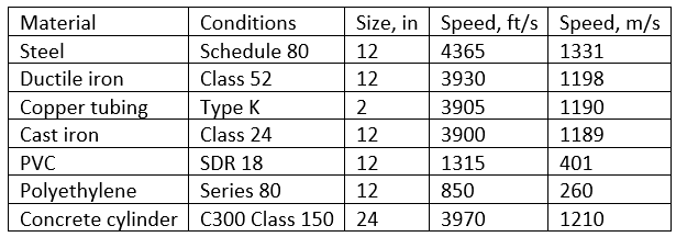
As pipe size increases, speed decreases slightly; as pressure class increases, speed increases.
While these wave speeds are based on sound theory and numerous experiments, there can be significant variations when real water and wastewater systems are involved. Most of this is due to small amounts of entrained gases in the fluid. These gases have the effect of absorbing wave energy and slowing down the wave. Whenever possible, it is good to collect calibration data to verify the model. Usually wave speed is a parameter that has a great influence on model results. HAMMER provides a Wave Speed Reduction Factor option to reduce wave speed when the pressure becomes low, and gases can come out of solution.
A good practice when there is uncertainty in wave speed is to run the model with a range of wave speeds. If the results are highly dependent on wave speed, it is worth further refining the input.
The help documentation in HAMMER describes the data entry for the Wave Speed Calculator which is found under the Home tab. More information can be found on Bentley Communities under Entering Pipe Wave Speed for a Transient Simulation.
Want to learn more from our resident water and wastewater expert? Join the Dr. Tom Walski Newsletter today!

