Choose Area of Interest
SEARCH SOFTWARE
Seismic rehabilitation of creeping ground using a sustainable micropiled PT raft Organization: GeoStruxer Location: Jazan, Saudi Arabia Project phase: Completed and operational Estimated project cost: USD 5.4 million with a 2.1 million cost savings from optimization Bentley software: PLAXIS, RAM...
by Edita Kemzuraite
by Breda Kiely
Are You Buying Effort or Value? Rethinking Transportation Resilience. Ask 10 people in transportation what “resilience” means, and you’ll likely get ten different answers. And that’s exactly the point: resilience isn’t one thing. It includes people, data, systems, contracts, materials,...
by Amy Heffner
Imagine a workflow as dynamic as the world you’re capturing. A process where your tools don’t dictate your path but adapt to your project’s unique demands. As an engineer, surveyor, or planner, you don’t just capture data; you create the...

by Aude Camus
by Jenna Carpentier
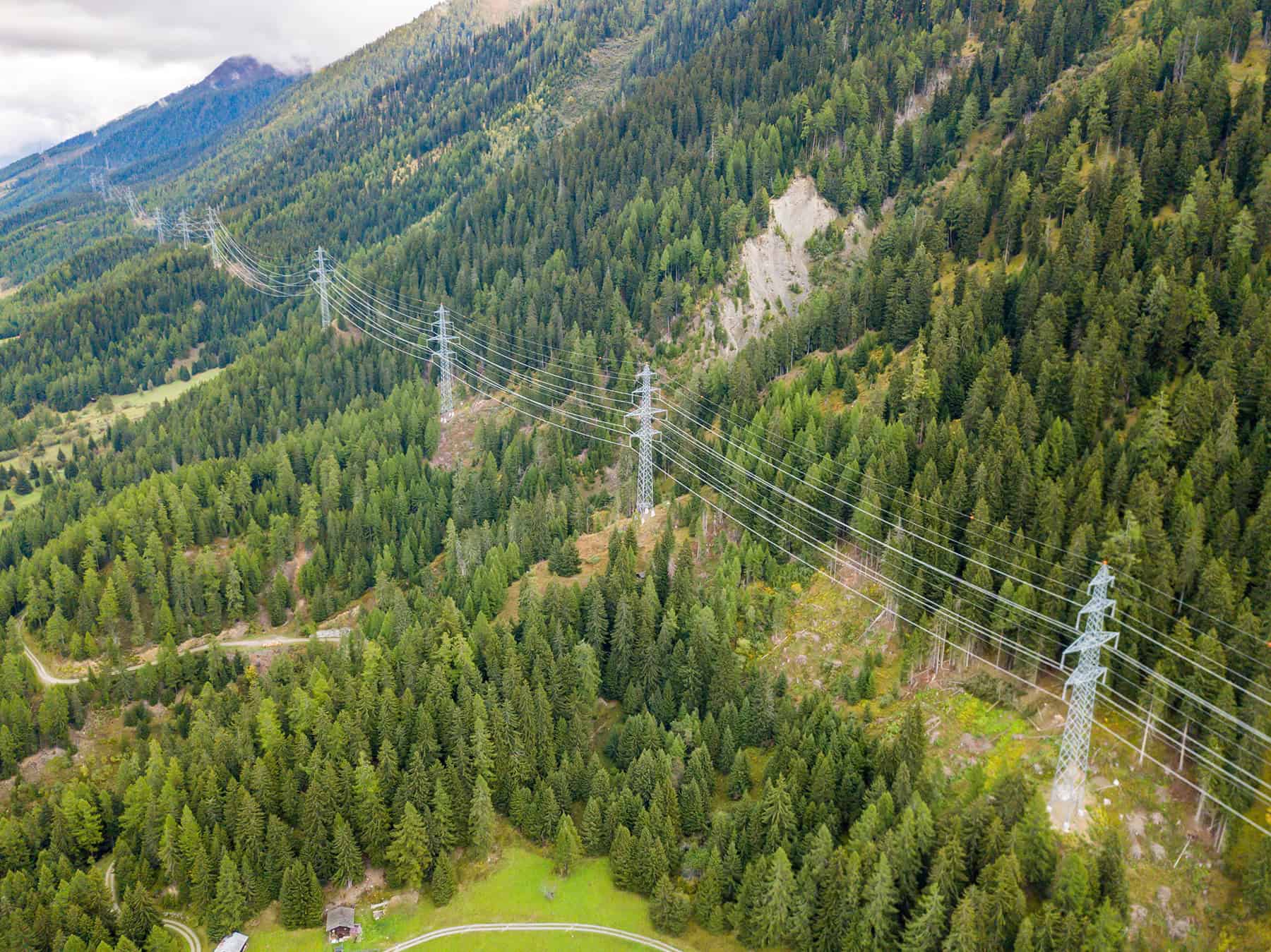
Europe’s complex energy ecosystem infrastructure: Why the grid needs modernization now Europe’s power grid is the largest interconnected grid in the world—and it’s under pressure. Climate risks, outdated infrastructure, cyberattacks, and growing demand for renewable energy are changing the energy...
by Martha Murillo
When most people look at transmission and distribution lines, they see a series of tall towers or poles with wires strung between them. But engineers? They see art. There’s beauty in the symmetry of structures and the geometric alignment of...
by Eleanore Nguyen-Locke
How Gen Z is shaping sustainable infrastructure careers During a recent call with my 19-year-old son, a college sophomore, we talked about his excitement to make a positive impact with his future profession. He feels passionately that he can and...

by Jena Shore
by Paul Rotter


