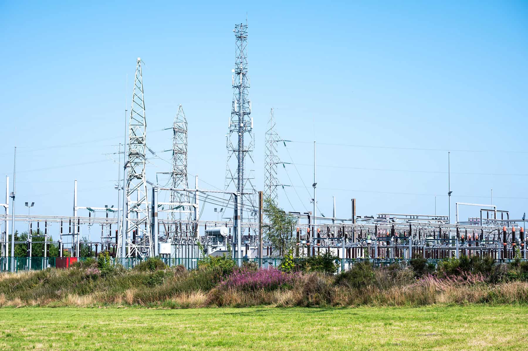
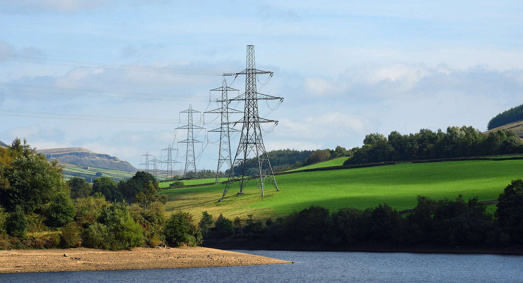
When most people look at transmission and distribution lines, they see a series of tall towers or poles with wires strung between them. But engineers? They see art.
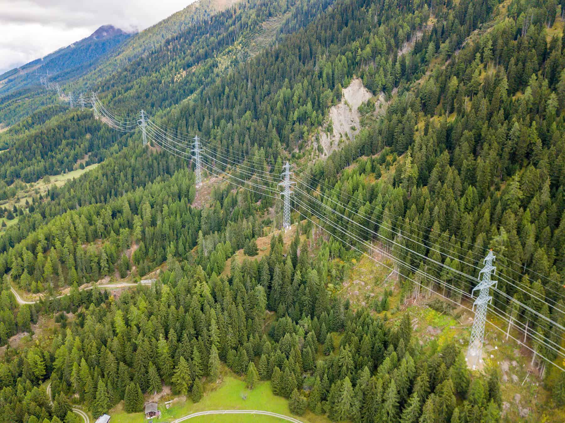
There’s beauty in the symmetry of structures and the geometric alignment of lines. Beyond the technical design, engineers appreciate how these systems interact with their surroundings—crossing rugged terrain, sweeping across open landscapes, or weaving through urban skylines. These lines don’t just serve a purpose, they follow the land in a way that blends engineering with aesthetics.
And behind this work of art lies a powerful industry tool that has been revolutionizing overhead power line design for over 40 years: Bentley’s PLS-CADD.
If you’ve ever wondered how engineers decide where to place each tower, how to minimize cost without compromising safety, or how to make the grid more resilient, here’s your peek behind the curtain. Spoiler alert: it’s not magic. It’s math, modeling, and one seriously powerful piece of software.
How PLS-CADD optimizes overhead line design
PLS-CADD (Power Line Systems – Computer Aided Design and Drafting) is the industry standard for overhead line design. But the real artistry comes from its Line Optimization feature within its Optimum Spotting module. Think of it as the finest brush in an artist’s set that eases the creation of a work of art.
By blending terrain data, structure libraries, and design standards, it creates layouts that are efficient, cost-effective, and resilient. This isn’t just automation. It’s intelligent, constraint-aware, multivariable optimization that saves engineering time, money, and headaches.
Inside the PLS-CADD optimization workflow
Like crafting a masterpiece, each step is a stroke of intention.
-
- Step 1: Define the vision
Engineers set the design parameters for voltages, safety clearances, and environmental conditions like wind and ice. These are the guiding principles of the composition. The canvas can be thought of as the alignment that is selected by engineers or routing professionals. Several routes can be selected for evaluation so the best solution can identified.
- Step 2: Incorporate the landscape
The terrain becomes the backdrop. Hills, rivers, roads, and trees are mapped in 3D, forming the contours of the scene. Constraints that would impact the siting of structures from the built environment (such as roads, buildings, and other power lines) and natural environment (such as wetlands, waterways, farmland, slope of the terrain) can be considered when spotting the structures.
- Step 3: Model the structures
From a palette of towers and poles, engineers select the configurations and strength requirements that will determine the structure locations based on the different capabilities of each type of structure.
- Step 4: Compose the design
PLS-CADD runs its optimization engine, testing thousands of layouts to find the most efficient design along the landscaped route.
- Step 5: Refine the Masterpiece
Engineers review the design, make adjustments if needed, and approve the final plan. The full bill of materials, including labor considerations, can be taken into account so a truly economical line design can be considered.
-
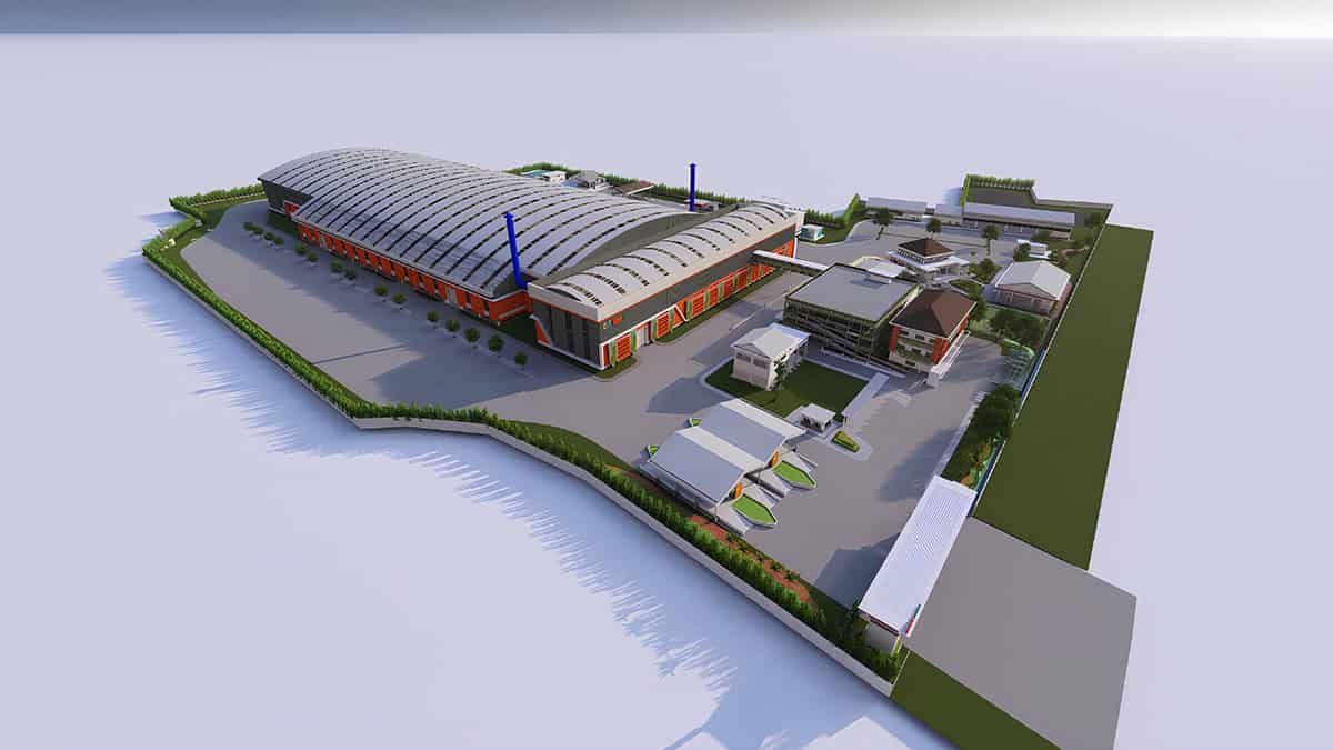
Voilà! You have a perfectly optimized power line design, as shown in the image below.
- Step 1: Define the vision

Why PLS-CADD is the go-to tool for engineers
Designs that once took weeks can now be completed in hours. Multiple routes and structure types for a line can now be evaluated in much shorter timeframes. Due to its unmatched efficiency and substantial time savings over manual spotting methods, PLS-CADD has earned its reputation as the go-to solution for overhead line design.
The optimum spotting process can be further enhanced by using TOWER to automatically select and model the appropriate tower body and leg extensions, ensuring the best fit for varying terrain. This capability is especially effective in sloping or mountainous areas, eliminating manual trial-and-error.
A similar tool is also available for PLS-POLE models for multipole structures.
Engineers trust PLS-CADD because it is:
- Intelligent—it considers real-world physics such as sag-tension, blowout or sway of the conductors and wires, actual terrain and obstacles along the route for spotting considerations, and structure strength.
- Scalable—whether it’s a two-mile distribution line or a 200-mile transmission corridor, PLS-CADD handles it. The Optimum Spotting module can be used for rebuilds where existing structure locations must be used to pick the appropriate structures that meet design constraints, which can be very effective in both urban and rural environments.
- Transparent—every decision is traceable, whether it is the design criteria used or the constraints that were considered when spotting. Every assumption is documented.
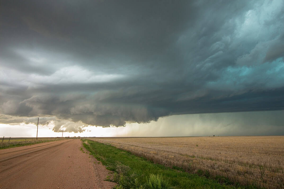
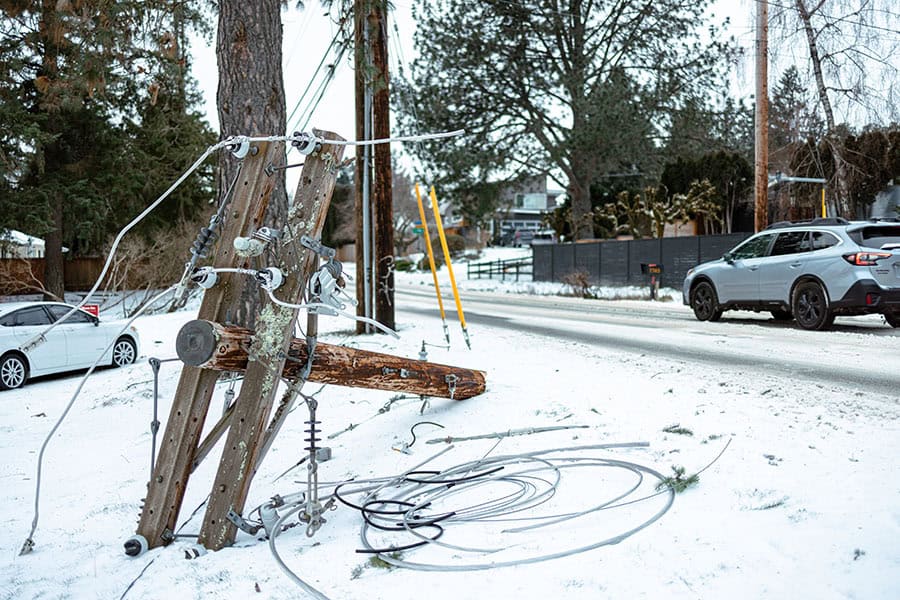
Case study: Storm recovery with Toth & Associates
Beyond its powerful optimum spotting capability, PLS-CADD gives engineers the tools to design overhead lines quickly, safely, and efficiently. Its impact is best illustrated by a restoration project led by engineering firm Toth & Associates in west-central Illinois.
In June 2023, a storm with 120-mile-per-hour winds destroyed 120 transmission poles across 6.5 miles, leaving 1,500 residents without power. Prairie Power faced the challenge of rebuilding an outdated 60-year-old line under tight deadlines and material shortages. Partnering with Toth & Associates, they used PLS-CADD as the digital backbone for rapid design, real-time adjustments, and automated safety checks. The software enabled quick respotting, respanning, and precise staking, ensuring reliability despite supply constraints. Continuous refinements based on field data streamlined construction. The team restored power 18 days ahead of schedule, demonstrating resilience and efficiency.

The bottom line
For decades, engineers have turned to PLS-CADD as their trusted companion in designing and maintaining overhead power lines. Its powerful capabilities help teams create lines that withstand extreme conditions, accelerate post-storm rebuilds, integrate renewable energy sources with minimal cost, and proactively address risks like clearance violations to obstacles, vegetation management and structure loading concerns. More than just software, PLS-CADD is the engineer’s tool for transforming a canvas of constraints into a sharp, well-designed work of infrastructure art. And as the industry continues to evolve, PLS-CADD remains the foundation engineers will rely on to meet tomorrow’s challenges with accuracy and confidence.
Ready to transform your overhead line designs from time-consuming tasks into optimized masterpieces? Learn more about how Bentley’s Power Line Systems and PLS-CADD can help you cut costs, improve resiliency, and accelerate project timelines.