Modeling pump status or speed or valve position is generally pretty straightforward in most automatically controlled systems. The modeler just needs to transport the typical PLC type controls over to the model using control statements that are essentially controls like
IF (Tank 2 level < 150) THEN (Pump 7 = ON)
Or
IF (Time > 6:00 am AND Time < 11:00 am) THEN (Valve 22 = Open)
In calibrating extended period system (EPS) models using this logic, it is usually easy to match system operation with model results. If there is a discrepancy, the problem usually lies in demands, not in the controls.
The Problem
However, matching system and model behavior in some systems can be much more complicated. The logic may be something like “If Pump 5 is running and the tank level is less than 20 ft and Pump 6 hasn’t been run for 2 days, then turn on Pump 6.” Even worse are human controlled systems where the logic may be along the lines of “It’s 2:17, it’s been pretty hot the last few days, and energy costs more in the afternoon, and yesterday I got yelled at because I let the south tank drop to far, but it’s not too low now, we had a turbidity complaint last night, and I need to go to the bathroom, so I’ll turn the pump on now.”
Typical control statements in hydraulic models don’t mimic those kinds of pump controls very well. Trying to calibrate an EPS model with this kind of control with control statements is difficult and even if the modeler gets it right today, it will probably not be very accurate tomorrow.
The modeler and those using the model must first realize that they will never quite get these controls perfect because there is so much difference from one day to the next that they will not be exact in pump status or valve operation. If the model is good, however, the overall flows and pressure should look acceptable, but the exact time of changes will most likely not match well. Nevertheless, the modeler does want some verification that the model worked well with the right controls.
This leads to a calibration question: “If I have the correct pump and valve behavior for a given historical period, how closely do modeled flows, pressures, and tank levels match the observed values?” If there is good agreement, that builds confidence in the network and demand assumptions, and efforts to improve forecasts can focus on building a reasonably representative control logic. If there is significant disagreement, then the network hydraulic properties and demand patterns should be investigated.
There are several options for answering this calibration question. The most straightforward is to pick a typical day and write out time based controls for that day. But this can be time-consuming for a system with many pumps and if the modeler wants to model a longer period, it can be very tedious.
There are some additional options in WaterGEMS and WaterCAD to control model elements outside the standard control statements.
Using the SCADAConnect Control Overrides interface, the modeler can manually add pump and valve status overrides much more efficiently than creating individual conventional controls. As shown below, a table of control overrides can be built, where the modeler simply identifies the Controlled Element (e.g. Pump 4), the Attribute (e.g. pump status, pump speed) to control, the Value (e.g. on, off), the start date/time when the override begins and its duration. The user interface is much easier than the normal Control editor. The user can simply use or ignore the statement by checking or unchecking the “Enabled” box.
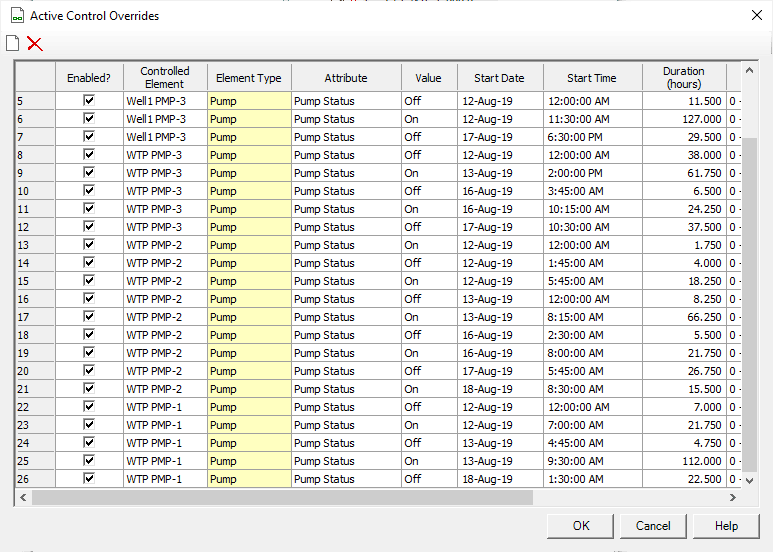
But WaterGEMS/WaterCAD have what is potentially an even easier approach if the historical SCADA system has signals for pump status or setting or valve setting. This table of control overrides can be automatically imported from SCADA signals, vastly reducing or eliminating the need for manual data entry. There are some advantages to this approach in that once the connection is set up, the model can run for one day or one month with the same mouse clicks.
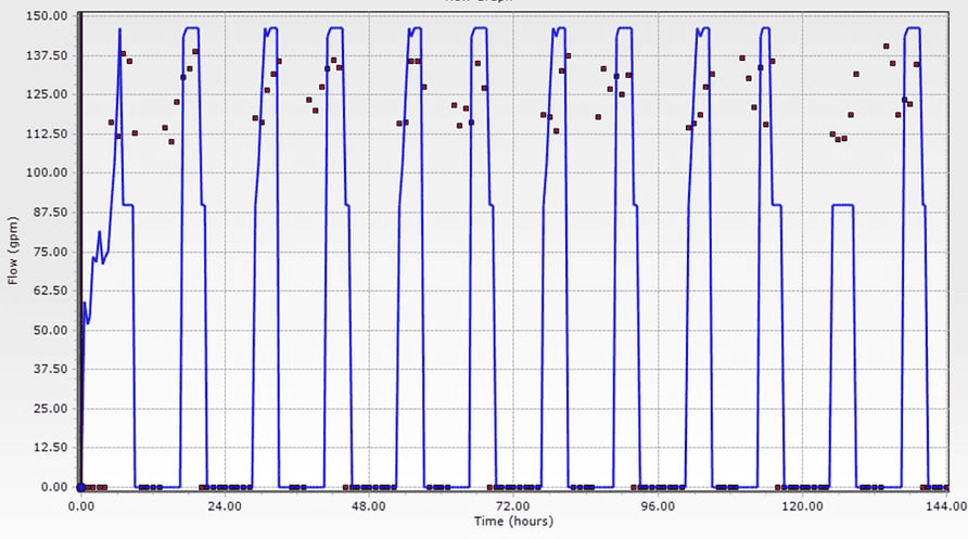
Once the control overrides have been established and the model has been computed for the specified historical period, the modeler can compare observed SCADA values such as flow, pressure, and tank levels throughout the system with the modeled results. In the example below, the red points are flows from the SCADA system while the blue lines are model results with pump status set by the SCADA system.
Steps To Solve The Problem
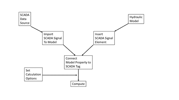
The steps in WaterGEMS to set up these runs with SCADA controlled elements are not difficult and consist of:
- Linking WaterGEMS to the SCADA Signal source.
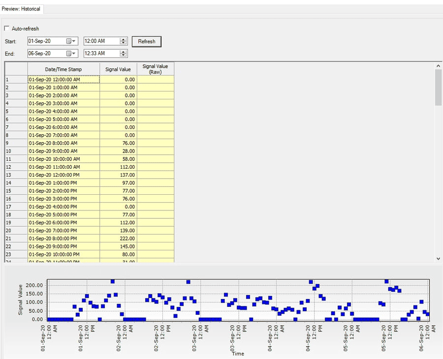
- Next the user needs to connect the SCADA Signals with a property for a model element. This is done with the SCADA Signal element.
This is where the modeler says that “Model pump PMP-3 flow is associated with SCADA signal tag (Pump #3)”.
3.Once the modeler has associated the SCADA Signal and the model property, set up the calculation options by:
- Setting the Calculation Type to SCADAConnnect Simulator
- Picking the SCADA Calculation Type (e.g. hydraulics only, age)
- Setting Simulation Mode to Historical
- Setting the Control Overrides to Active
- Setting Automatically Import Control Overrides to True
- Picking the simulation start date and duration
In summary, the overall process to set up control overrides from SCADA data looks like this:
The Results
Now, when a scenario is computed with these calculation options, the pumps will be controlled by status or speed from the SCADA signals.
This can be very helpful in those cases where standard control statements don’t work well, and it’s desired to calibrate an EPS model with a lot of pumps. This works well for any kind of situation where the user has access to SCADA data such as trying to apply an EPS model to understand pump/tank interactions, energy costs or water quality, where an accurate EPS model is the basis for the calculations.
Want to learn more from our resident water and wastewater expert? Join the Dr. Tom Walski Newsletter today!


