In order to do any kind of hydraulic modeling, whether it is for water distribution, sewage or stormwater, it is necessary to determine the head loss over a range of flow rates. Much of the early days of hydraulic engineering were consumed with engineers trying to come up with the right equation to do these calculations.
In the case of laminar flow, it is possible to derive a theoretically correct equation, the Hagen-Poiseuille equation, from the starting point of F = ma. However, the overwhelming portion of flows in real water systems are in the turbulent flow range such that it’s not possible to come up with a single analytical expression. Many, many have tried.
Darcy – Weisbach Equation
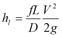
Turbulent flow head loss equations always contain some type of empirical coefficient to account for drag along the wall and the relative importance of inertial vs. viscous forces. Most would agree that the most theoretically correct equation is the Darcy-Weisbach equation. It is based on a balance of driving forces from pressure gradient and slope compared with the viscous and drag forces that restrict flow.
Where h is head loss, f is friction factor, L is length, D is diameter, V is velocity and g is gravity coefficient.
The Darcy-Weisbach equation dates to the mid-19th century. The Darcy-Weisbach equation uses a friction factor, f, to account for all the things that affect head less. It took many years to develop formulas for calculating f, because the behavior of the boundary layer depending on whether the boundary layer was smooth or rough.
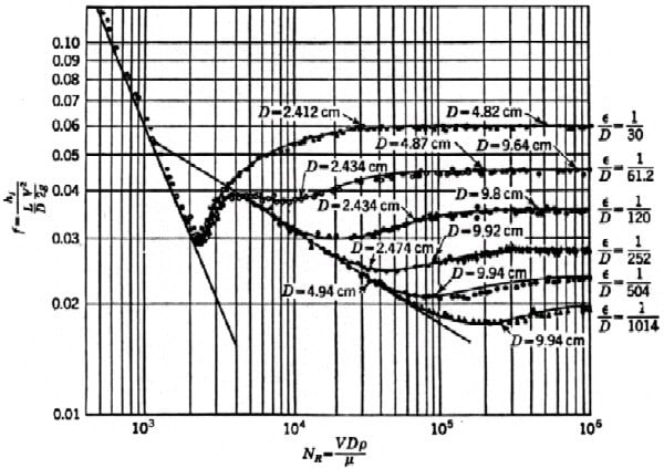
It took some insightful researchers to realize that what was happening at the boundary layer between the conduit and the fluid was crucial in determining head loss. It took a lot of experiments by researchers like Johan Nikuradse and others t understand what controlled f. The results of Nikuradse’s famous experiment are shown below.
Numerous other researchers extended the range of Reynolds Numbers and roughness, and eventually Colebrook and White came up with the equation for determining f. The Colebrook-White equation shown below is not a nice equation in that it can’t be solved directly for f but requires and iterative solution.
Where ε = roughness height, Re = Reynolds number
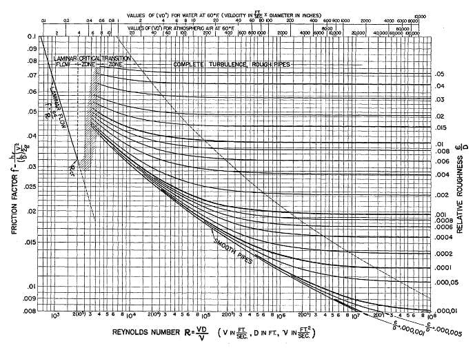
This was difficult for manual calculations, so a Princeton Professor, Lewis Moody, came up with the (now infamous for students) Moody diagram in the 1940s.
Since then, there have been numerous explicit approximations to the Colebrook-White equation. The most widely used s the Swamee-Jain equation from the 1970s.
Hazen-Williams Equation
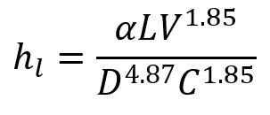
Meanwhile, back in the early 1900’s, two American engineers, Allen Hazen and G. S. Williams developed their own equation.
It had some odd exponents and its own empirical coefficient, C, but it was widely adopted, primarily because unlike the unwieldy f, the value of C was relatively constant for a given type of pipe. It became the equation of choice for most water engineers for pressure piping.
The Hazen-Williams equation had its shortcomings. It was most accurate for relatively smooth pipes with relatively large Reynolds numbers. However, it wasn’t very inaccurate when some of those assumptions were violated. For any conduit, there is some velocity and Reynolds number where the Hazen-Williams and Darcy-Weisbach equation will give the same results. As conditions deviate from that, then the results will deviate, but in most cases for typical water and wastewater applications, the deviations are not large.
Manning Equation
Meanwhile, engineers working in open channels and partly filled pipes have generally preferred the Manning equation. It is an extension of Chezy’s equation and what is called the Manning equation today is a simplification of Manning’s original equation developed by Glauckler.
The empirical coefficient in Manning’s equation is Manning’s n. Values have been calculated for a wide range of conduit materials. It tends to be a good approximation to the Darcy-Weisbach equation for large Reynolds numbers and roughness.
Kutter’s Equation
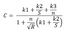
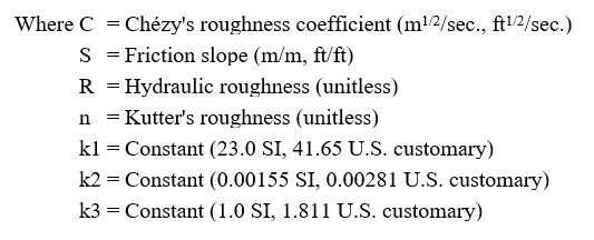
Kutter’s equation is a formula to determine the C value in the Chezy equation below (This is a different C than the Hazen-Williams C ). The n values in the Chezy equation are the same as the Manning equation.
Summary
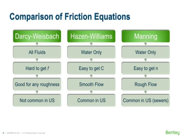
Each equation has its strengths and weaknesses and every engineer has his/her favorite equation. Since the Hazen-Williams and Manning equations were developed for water, their use for other fluids is questionable (although corrections can be made). The Darcy-Weisbach equation can be used for any Newtonian, single phase fluid. The table below summarizes the pros and cons of each equation.
In case you’re wondering, WaterGEMS and WaterCAD can choose between the Darcy-Weisbach, Hazen-Williams and Manning equations. For users of SewerGEMS, SewerCAD, Civil Storm and StormCAD, the equations available depend on the numerical solver selected but most are supported. OpenFlows FlowMaster allows the user to specify Darcy-Weisbach, Hazen-Williams, Manning and Kutter’s equations.
Much of the material for this blog was taken from a session at the 2016 EWRI Conference based on papers by Lindell Ormsbee and me, both called “Darcy Weisbach vs. Hazen Williams” where we debated the merits of each equation.
If you want to look up past blogs, go to https://blog.bentley.com/category/hydraulics-and-hydrology/. And if you want to contact me (Tom), you can email [email protected].
Want to learn more from our resident water and wastewater expert? Join the Dr. Tom Walski Newsletter today!


